6.6 Bilinear Patches

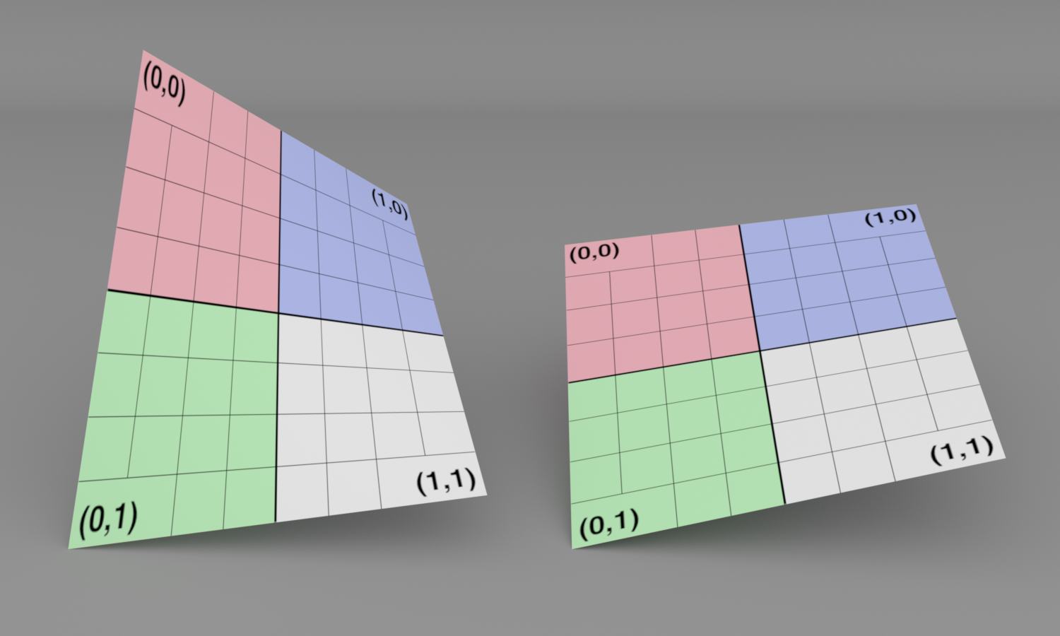
It is useful to have a shape defined by four vertices. One option would be a planar quadrilateral, though not requiring all four vertices to be coplanar is preferable, as it is less restrictive. Such a shape is the bilinear patch, which is a parametric surface defined by four vertices normal p Subscript 0 comma 0 , normal p Subscript 1 comma 0 , normal p Subscript 0 comma 1 , and normal p Subscript 1 comma 1 . Each vertex gives the position associated with a corner of the parametric left-parenthesis u comma v right-parenthesis domain left-bracket 0 comma 1 right-bracket squared and points on the surface are defined via bilinear interpolation:

f left-parenthesis u comma v right-parenthesis equals left-parenthesis 1 minus u right-parenthesis left-parenthesis 1 minus v right-parenthesis normal p Subscript 0 comma 0 Baseline plus u left-parenthesis 1 minus v right-parenthesis normal p Subscript 1 comma 0 Baseline plus left-parenthesis 1 minus u right-parenthesis v normal p Subscript 0 comma 1 Baseline plus u v normal p Subscript 1 comma 1 Baseline period

The bilinear patch is a doubly ruled surface: there are two straight lines through every point on it. (This can be seen by considering a parametric point on the surface left-parenthesis u comma v right-parenthesis and then fixing either of u and v and considering the function that results: it is linear.)

Not only can bilinear patches be used to represent planar quadrilaterals, but they can also represent simple curved surfaces. They are a useful target for converting higher-order parametric surfaces to simpler shapes that are amenable to direct ray intersection. Figure 6.22 shows two bilinear patches.

Figure 6.22: Two Bilinear Patches. The bilinear patch is defined by four vertices that are not necessarily planar. It is able to represent a variety of simple curved surfaces.

pbrt allows the specification of bilinear patch meshes for the same reasons that triangle meshes can be specified: to allow per-vertex attributes like position and surface normal to be shared by multiple patches and to allow mesh-wide properties to be stored just once. To this end, BilinearPatchMesh plays the equivalent role to the TriangleMesh.

<<BilinearPatchMesh Definition>>= 
class BilinearPatchMesh { public: <<BilinearPatchMesh Public Methods>> 
BilinearPatchMesh(const Transform &renderFromObject, bool reverseOrientation, std::vector<int> vertexIndices, std::vector<Point3f> p, std::vector<Normal3f> N, std::vector<Point2f> uv, std::vector<int> faceIndices, PiecewiseConstant2D *imageDist, Allocator alloc); std::string ToString() const; static void Init(Allocator alloc);
<<BilinearPatchMesh Public Members>> 
bool reverseOrientation, transformSwapsHandedness; int nPatches, nVertices; const int *vertexIndices = nullptr; const Point3f *p = nullptr; const Normal3f *n = nullptr; const Point2f *uv = nullptr; PiecewiseConstant2D *imageDistribution;
};

We will skip past the BilinearPatchMesh constructor, as it mirrors the TriangleMesh’s, transforming the positions and normals to rendering space and using the BufferCache to avoid storing redundant buffers in memory.

<<BilinearPatchMesh Public Members>>= 
bool reverseOrientation, transformSwapsHandedness; int nPatches, nVertices; const int *vertexIndices = nullptr; const Point3f *p = nullptr; const Normal3f *n = nullptr; const Point2f *uv = nullptr;

The BilinearPatch class implements the Shape interface and represents a single patch in a bilinear patch mesh.

<<BilinearPatch Definition>>= 
class BilinearPatch { public: <<BilinearPatch Public Methods>> 
BilinearPatch(const BilinearPatchMesh *mesh, int meshIndex, int blpIndex); static void Init(Allocator alloc); static BilinearPatchMesh *CreateMesh(const Transform *renderFromObject, bool reverseOrientation, const ParameterDictionary &parameters, const FileLoc *loc, Allocator alloc); static pstd::vector<Shape> CreatePatches(const BilinearPatchMesh *mesh, Allocator alloc); PBRT_CPU_GPU Bounds3f Bounds() const; PBRT_CPU_GPU pstd::optional<ShapeIntersection> Intersect(const Ray &ray, Float tMax = Infinity) const; PBRT_CPU_GPU bool IntersectP(const Ray &ray, Float tMax = Infinity) const; PBRT_CPU_GPU pstd::optional<ShapeSample> Sample(const ShapeSampleContext &ctx, Point2f u) const; PBRT_CPU_GPU Float PDF(const ShapeSampleContext &ctx, Vector3f wi) const; PBRT_CPU_GPU pstd::optional<ShapeSample> Sample(Point2f u) const; PBRT_CPU_GPU Float PDF(const Interaction &) const; PBRT_CPU_GPU DirectionCone NormalBounds() const; std::string ToString() const; Float Area() const { return area; } static SurfaceInteraction InteractionFromIntersection( const BilinearPatchMesh *mesh, int blpIndex, Point2f uv, Float time, Vector3f wo) { <<Compute bilinear patch point normal p Subscript , partial-differential normal p slash partial-differential u , and partial-differential normal p slash partial-differential v for left-parenthesis u comma v right-parenthesis >> 
<<Get bilinear patch vertices in p00, p01, p10, and p11>> 
const int *v = &mesh->vertexIndices[4 * blpIndex]; Point3f p00 = mesh->p[v[0]], p10 = mesh->p[v[1]]; Point3f p01 = mesh->p[v[2]], p11 = mesh->p[v[3]];
Point3f p = Lerp(uv[0], Lerp(uv[1], p00, p01), Lerp(uv[1], p10, p11)); Vector3f dpdu = Lerp(uv[1], p10, p11) - Lerp(uv[1], p00, p01); Vector3f dpdv = Lerp(uv[0], p01, p11) - Lerp(uv[0], p00, p10);
<<Compute left-parenthesis s comma t right-parenthesis texture coordinates at bilinear patch left-parenthesis u comma v right-parenthesis >> 
Point2f st = uv; Float duds = 1, dudt = 0, dvds = 0, dvdt = 1; if (mesh->uv) { <<Compute texture coordinates for bilinear patch intersection point>> 
Point2f uv00 = mesh->uv[v[0]], uv10 = mesh->uv[v[1]]; Point2f uv01 = mesh->uv[v[2]], uv11 = mesh->uv[v[3]]; st = Lerp(uv[0], Lerp(uv[1], uv00, uv01), Lerp(uv[1], uv10, uv11));
<<Update bilinear patch partial-differential normal p slash partial-differential u and partial-differential normal p slash partial-differential v accounting for left-parenthesis s comma t right-parenthesis >> 
<<Compute partial derivatives of left-parenthesis u comma v right-parenthesis with respect to left-parenthesis s comma t right-parenthesis >> 
Vector2f dstdu = Lerp(uv[1], uv10, uv11) - Lerp(uv[1], uv00, uv01); Vector2f dstdv = Lerp(uv[0], uv01, uv11) - Lerp(uv[0], uv00, uv10); duds = std::abs(dstdu[0]) < 1e-8f ? 0 : 1 / dstdu[0]; dvds = std::abs(dstdv[0]) < 1e-8f ? 0 : 1 / dstdv[0]; dudt = std::abs(dstdu[1]) < 1e-8f ? 0 : 1 / dstdu[1]; dvdt = std::abs(dstdv[1]) < 1e-8f ? 0 : 1 / dstdv[1];
<<Compute partial derivatives of normal p Subscript with respect to left-parenthesis s comma t right-parenthesis >> 
Vector3f dpds = dpdu * duds + dpdv * dvds; Vector3f dpdt = dpdu * dudt + dpdv * dvdt;
<<Set dpdu and dpdv to updated partial derivatives>> 
if (Cross(dpds, dpdt) != Vector3f(0, 0, 0)) { if (Dot(Cross(dpdu, dpdv), Cross(dpds, dpdt)) < 0) dpdt = -dpdt; dpdu = dpds; dpdv = dpdt; }
}
<<Find partial derivatives partial-differential bold n Subscript slash partial-differential u and partial-differential bold n Subscript slash partial-differential v for bilinear patch>> 
Vector3f d2Pduu(0, 0, 0), d2Pdvv(0, 0, 0); Vector3f d2Pduv = (p00 - p01) + (p11 - p10); <<Compute coefficients for fundamental forms>> 
Float E = Dot(dpdu, dpdu), F = Dot(dpdu, dpdv), G = Dot(dpdv, dpdv); Vector3f n = Normalize(Cross(dpdu, dpdv)); Float e = Dot(n, d2Pduu), f = Dot(n, d2Pduv), g = Dot(n, d2Pdvv);
<<Compute partial-differential bold n Subscript slash partial-differential u and partial-differential bold n Subscript slash partial-differential v from fundamental form coefficients>> 
Float EGF2 = DifferenceOfProducts(E, G, F, F); Float invEGF2 = (EGF2 == 0) ? Float(0) : 1 / EGF2; Normal3f dndu = Normal3f((f * F - e * G) * invEGF2 * dpdu + (e * F - f * E) * invEGF2 * dpdv); Normal3f dndv = Normal3f((g * F - f * G) * invEGF2 * dpdu + (f * F - g * E) * invEGF2 * dpdv);
<<Update partial-differential bold n Subscript slash partial-differential u and partial-differential bold n Subscript slash partial-differential v to account for left-parenthesis s comma t right-parenthesis parameterization>> 
Normal3f dnds = dndu * duds + dndv * dvds; Normal3f dndt = dndu * dudt + dndv * dvdt; dndu = dnds; dndv = dndt;
<<Initialize bilinear patch intersection point error pError>> 
Point3f pAbsSum = Abs(p00) + Abs(p01) + Abs(p10) + Abs(p11); Vector3f pError = gamma(6) * Vector3f(pAbsSum);
<<Initialize SurfaceInteraction for bilinear patch intersection>> 
bool flipNormal = mesh->reverseOrientation ^ mesh->transformSwapsHandedness; SurfaceInteraction isect(Point3fi(p, pError), st, wo, dpdu, dpdv, dndu, dndv, time, flipNormal);
<<Compute bilinear patch shading normal if necessary>> 
if (mesh->n) { <<Compute shading normals for bilinear patch intersection point>> 
Normal3f n00 = mesh->n[v[0]], n10 = mesh->n[v[1]]; Normal3f n01 = mesh->n[v[2]], n11 = mesh->n[v[3]]; Normal3f ns = Lerp(uv[0], Lerp(uv[1], n00, n01), Lerp(uv[1], n10, n11)); if (LengthSquared(ns) > 0) { ns = Normalize(ns); <<Set shading geometry for bilinear patch intersection>> 
Normal3f dndu = Lerp(uv[1], n10, n11) - Lerp(uv[1], n00, n01); Normal3f dndv = Lerp(uv[0], n01, n11) - Lerp(uv[0], n00, n10); <<Update partial-differential bold n Subscript slash partial-differential u and partial-differential bold n Subscript slash partial-differential v to account for left-parenthesis s comma t right-parenthesis parameterization>> 
Normal3f dnds = dndu * duds + dndv * dvds; Normal3f dndt = dndu * dudt + dndv * dvdt; dndu = dnds; dndv = dndt;
Transform r = RotateFromTo(Vector3f(Normalize(isect.n)), Vector3f(ns)); isect.SetShadingGeometry(ns, r(dpdu), r(dpdv), dndu, dndv, true);
}
}
return isect; }
private: <<BilinearPatch Private Methods>> 
const BilinearPatchMesh *GetMesh() const { return (*allMeshes)[meshIndex]; } bool IsRectangle(const BilinearPatchMesh *mesh) const { <<Get bilinear patch vertices in p00, p01, p10, and p11>> 
const int *v = &mesh->vertexIndices[4 * blpIndex]; Point3f p00 = mesh->p[v[0]], p10 = mesh->p[v[1]]; Point3f p01 = mesh->p[v[2]], p11 = mesh->p[v[3]];
if (p00 == p01 || p01 == p11 || p11 == p10 || p10 == p00) return false; <<Check if bilinear patch vertices are coplanar>> 
Normal3f n(Normalize(Cross(p10 - p00, p01 - p00))); if (AbsDot(Normalize(p11 - p00), n) > 1e-5f) return false;
<<Check if planar vertices form a rectangle>> 
Point3f pCenter = (p00 + p01 + p10 + p11) / 4; Float d2[4] = { DistanceSquared(p00, pCenter), DistanceSquared(p01, pCenter), DistanceSquared(p10, pCenter), DistanceSquared(p11, pCenter) }; for (int i = 1; i < 4; ++i) if (std::abs(d2[i] - d2[0]) / d2[0] > 1e-4f) return false; return true;
}
<<BilinearPatch Private Members>> 
int meshIndex, blpIndex; static pstd::vector<const BilinearPatchMesh *> *allMeshes; Float area; static constexpr Float MinSphericalSampleArea = 1e-4;
};

<<BilinearPatch Method Definitions>>= 
BilinearPatch::BilinearPatch(const BilinearPatchMesh *mesh, int meshIndex, int blpIndex) : meshIndex(meshIndex), blpIndex(blpIndex) { <<Store area of bilinear patch in area>> 
<<Get bilinear patch vertices in p00, p01, p10, and p11>> 
const int *v = &mesh->vertexIndices[4 * blpIndex]; Point3f p00 = mesh->p[v[0]], p10 = mesh->p[v[1]]; Point3f p01 = mesh->p[v[2]], p11 = mesh->p[v[3]];
if (IsRectangle(mesh)) area = Distance(p00, p01) * Distance(p00, p10); else { <<Compute approximate area of bilinear patch>> 
// FIXME: it would be good to skip this for flat patches, or to // be adaptive based on curvature in some manner constexpr int na = 3; Point3f p[na + 1][na + 1]; for (int i = 0; i <= na; ++i) { Float u = Float(i) / Float(na); for (int j = 0; j <= na; ++j) { Float v = Float(j) / Float(na); p[i][j] = Lerp(u, Lerp(v, p00, p01), Lerp(v, p10, p11)); } } area = 0; for (int i = 0; i < na; ++i) for (int j = 0; j < na; ++j) area += 0.5f * Length(Cross(p[i + 1][j + 1] - p[i][j], p[i + 1][j] - p[i][j + 1]));
}
}

Also similar to triangles, each BilinearPatch stores the index of the mesh that it is a part of as well as its own index in the mesh’s patches.

<<BilinearPatch Private Members>>= 
int meshIndex, blpIndex;

The GetMesh() method makes it easy for a BilinearPatch to get the pointer to its associated mesh.

<<BilinearPatch Private Methods>>= 
const BilinearPatchMesh *GetMesh() const { return (*allMeshes)[meshIndex]; }

There is a subtlety that comes with the use of a vector to store the meshes. pbrt’s scene initialization code in Appendix C does its best to parallelize its work, which includes the parallelization of reading binary files that encode meshes from disk. A mutex is used to protect adding meshes to this vector, though as this vector grows, it is periodically reallocated to make more space. A consequence is that the BilinearPatch constructor must not call the GetMesh() method to get its BilinearPatchMesh *, since GetMesh() accesses allMeshes without mutual exclusion. Thus, the mesh is passed to the constructor as a parameter above.

<<BilinearPatch Private Members>>+=  
static pstd::vector<const BilinearPatchMesh *> *allMeshes;

The area of a parametric surface defined over left-bracket 0 comma 1 right-bracket squared is given by the integral

integral Subscript 0 Superscript 1 Baseline integral Subscript 0 Superscript 1 Baseline double-vertical-bar StartFraction partial-differential normal p Over partial-differential u EndFraction times StartFraction partial-differential normal p Over partial-differential v EndFraction double-vertical-bar normal d u normal d v period

The partial derivatives of a bilinear patch are easily derived. They are:

StartLayout 1st Row 1st Column StartFraction partial-differential normal p Over partial-differential u EndFraction 2nd Column equals left-parenthesis 1 minus v right-parenthesis left-parenthesis normal p Subscript 1 comma 0 Baseline minus normal p Subscript 0 comma 0 Baseline right-parenthesis plus v left-parenthesis normal p Subscript 1 comma 1 Baseline minus normal p Subscript 0 comma 1 Baseline right-parenthesis 2nd Row 1st Column StartFraction partial-differential normal p Over partial-differential v EndFraction 2nd Column equals left-parenthesis 1 minus u right-parenthesis left-parenthesis normal p Subscript 0 comma 1 Baseline minus normal p Subscript 0 comma 0 Baseline right-parenthesis plus u left-parenthesis normal p Subscript 1 comma 1 Baseline minus normal p Subscript 1 comma 0 Baseline right-parenthesis period EndLayout

However, it is not generally possible to evaluate the area integral from Equation (6.12) in closed form with these partial derivatives. Therefore, the BilinearPatch constructor caches the patch’s surface area in a member variable, using numerical integration to compute its value if necessary.

Because bilinear patches are often used to represent rectangles, the constructor checks for that case and takes the product of the lengths of the sides of the rectangle to compute the area when appropriate. In the general case, the fragment <<Compute approximate area of bilinear patch>> uses a Riemann sum evaluated at 3 times 3 points to approximate Equation (6.12). We do not include that code fragment here.

<<Store area of bilinear patch in area>>= 
<<Get bilinear patch vertices in p00, p01, p10, and p11>> 
const int *v = &mesh->vertexIndices[4 * blpIndex]; Point3f p00 = mesh->p[v[0]], p10 = mesh->p[v[1]]; Point3f p01 = mesh->p[v[2]], p11 = mesh->p[v[3]];
if (IsRectangle(mesh)) area = Distance(p00, p01) * Distance(p00, p10); else { <<Compute approximate area of bilinear patch>> 
// FIXME: it would be good to skip this for flat patches, or to // be adaptive based on curvature in some manner constexpr int na = 3; Point3f p[na + 1][na + 1]; for (int i = 0; i <= na; ++i) { Float u = Float(i) / Float(na); for (int j = 0; j <= na; ++j) { Float v = Float(j) / Float(na); p[i][j] = Lerp(u, Lerp(v, p00, p01), Lerp(v, p10, p11)); } } area = 0; for (int i = 0; i < na; ++i) for (int j = 0; j < na; ++j) area += 0.5f * Length(Cross(p[i + 1][j + 1] - p[i][j], p[i + 1][j] - p[i][j + 1]));
}

<<BilinearPatch Private Members>>+=  
Float area;

This fragment, which loads the four vertices of a patch into local variables, will be reused in many of the following methods.

<<Get bilinear patch vertices in p00, p01, p10, and p11>>= 
const int *v = &mesh->vertexIndices[4 * blpIndex]; Point3f p00 = mesh->p[v[0]], p10 = mesh->p[v[1]]; Point3f p01 = mesh->p[v[2]], p11 = mesh->p[v[3]];

In addition to the surface area computation, there will be a number of additional cases where we will find it useful to use specialized algorithms if a BilinearPatch is a rectangle. Therefore, this check is encapsulated in the IsRectangle() method.

It first tests to see if any two neighboring vertices are coincident, in which case the patch is certainly not a rectangle. This check is important to perform first, since the following ones would otherwise end up trying to perform invalid operations like normalizing degenerate vectors in that case.

<<BilinearPatch Private Methods>>+= 
bool IsRectangle(const BilinearPatchMesh *mesh) const { <<Get bilinear patch vertices in p00, p01, p10, and p11>> 
const int *v = &mesh->vertexIndices[4 * blpIndex]; Point3f p00 = mesh->p[v[0]], p10 = mesh->p[v[1]]; Point3f p01 = mesh->p[v[2]], p11 = mesh->p[v[3]];
if (p00 == p01 || p01 == p11 || p11 == p10 || p10 == p00) return false; <<Check if bilinear patch vertices are coplanar>> 
Normal3f n(Normalize(Cross(p10 - p00, p01 - p00))); if (AbsDot(Normalize(p11 - p00), n) > 1e-5f) return false;
<<Check if planar vertices form a rectangle>> 
Point3f pCenter = (p00 + p01 + p10 + p11) / 4; Float d2[4] = { DistanceSquared(p00, pCenter), DistanceSquared(p01, pCenter), DistanceSquared(p10, pCenter), DistanceSquared(p11, pCenter) }; for (int i = 1; i < 4; ++i) if (std::abs(d2[i] - d2[0]) / d2[0] > 1e-4f) return false; return true;
}

If the four vertices are not coplanar, then they do not form a rectangle. We can check this case by computing the surface normal of the plane formed by three of the vertices and then testing if the vector from one of those three to the fourth vertex is not (nearly) perpendicular to the plane normal.

<<Check if bilinear patch vertices are coplanar>>= 
Normal3f n(Normalize(Cross(p10 - p00, p01 - p00))); if (AbsDot(Normalize(p11 - p00), n) > 1e-5f) return false;

Four coplanar vertices form a rectangle if they all have the same distance from the average of their positions. The implementation here computes the squared distance to save the square root operations and then tests the relative error with respect to the first squared distance. Because the test is based on relative error, it is not sensitive to the absolute size of the patch; scaling all the vertex positions does not affect it.

<<Check if planar vertices form a rectangle>>= 
Point3f pCenter = (p00 + p01 + p10 + p11) / 4; Float d2[4] = { DistanceSquared(p00, pCenter), DistanceSquared(p01, pCenter), DistanceSquared(p10, pCenter), DistanceSquared(p11, pCenter) }; for (int i = 1; i < 4; ++i) if (std::abs(d2[i] - d2[0]) / d2[0] > 1e-4f) return false; return true;

With the area cached, implementation of the Area() method is trivial.

<<BilinearPatch Public Methods>>= 
Float Area() const { return area; }

The bounds of a bilinear patch are given by the bounding box that bounds its four corner vertices. As with Triangles, the mesh vertices are already in rendering space, so no further transformation is necessary here.

<<BilinearPatch Method Definitions>>+=  
Bounds3f BilinearPatch::Bounds() const { const BilinearPatchMesh *mesh = GetMesh(); <<Get bilinear patch vertices in p00, p01, p10, and p11>> 
const int *v = &mesh->vertexIndices[4 * blpIndex]; Point3f p00 = mesh->p[v[0]], p10 = mesh->p[v[1]]; Point3f p01 = mesh->p[v[2]], p11 = mesh->p[v[3]];
return Union(Bounds3f(p00, p01), Bounds3f(p10, p11)); }

Although a planar patch has a single surface normal, the surface normal of a nonplanar patch varies across its surface.

<<BilinearPatch Method Definitions>>+=  
DirectionCone BilinearPatch::NormalBounds() const { const BilinearPatchMesh *mesh = GetMesh(); <<Get bilinear patch vertices in p00, p01, p10, and p11>> 
const int *v = &mesh->vertexIndices[4 * blpIndex]; Point3f p00 = mesh->p[v[0]], p10 = mesh->p[v[1]]; Point3f p01 = mesh->p[v[2]], p11 = mesh->p[v[3]];
<<If patch is a triangle, return bounds for single surface normal>> 
if (p00 == p10 || p10 == p11 || p11 == p01 || p01 == p00) { Vector3f dpdu = Lerp(0.5f, p10, p11) - Lerp(0.5f, p00, p01); Vector3f dpdv = Lerp(0.5f, p01, p11) - Lerp(0.5f, p00, p10); Vector3f n = Normalize(Cross(dpdu, dpdv)); if (mesh->n) { Normal3f ns = (mesh->n[v[0]] + mesh->n[v[1]] + mesh->n[v[2]] + mesh->n[v[3]]) / 4; n = FaceForward(n, ns); } else if (mesh->reverseOrientation ^ mesh->transformSwapsHandedness) n = -n; return DirectionCone(n); }
<<Compute bilinear patch normal n00 at left-parenthesis 0 comma 0 right-parenthesis >> 
Vector3f n00 = Normalize(Cross(p10 - p00, p01 - p00)); if (mesh->n) n00 = FaceForward(n00, mesh->n[v[0]]); else if (mesh->reverseOrientation ^ mesh->transformSwapsHandedness) n00 = -n00;
<<Compute bilinear patch normals n10, n01, and n11>> 
Vector3f n10 = Normalize(Cross(p11 - p10, p00 - p10)); Vector3f n01 = Normalize(Cross(p00 - p01, p11 - p01)); Vector3f n11 = Normalize(Cross(p01 - p11, p10 - p11)); if (mesh->n) { n10 = FaceForward(n10, mesh->n[v[1]]); n01 = FaceForward(n01, mesh->n[v[2]]); n11 = FaceForward(n11, mesh->n[v[3]]); } else if (mesh->reverseOrientation ^ mesh->transformSwapsHandedness) { n10 = -n10; n01 = -n01; n11 = -n11; }
<<Compute average normal and return normal bounds for patch>> 
Vector3f n = Normalize(n00 + n10 + n01 + n11); Float cosTheta = std::min({Dot(n, n00), Dot(n, n01), Dot(n, n10), Dot(n, n11)}); return DirectionCone(n, Clamp(cosTheta, -1, 1));
}

If the bilinear patch is actually a triangle, the <<If patch is a triangle, return bounds for single surface normal>> fragment evaluates its surface normal and returns the corresponding DirectionCone. We have not included that straightforward fragment here.

Otherwise, the normals are computed at the four corners of the patch. The following fragment computes the normal at the left-parenthesis 0 comma 0 right-parenthesis parametric position. It is particularly easy to evaluate the partial derivatives at the corners; they work out to be the differences with the adjacent vertices in u and v . Some care is necessary with the orientation of the normals, however. As with triangle meshes, if per-vertex shading normals were specified, they determine which side of the surface the geometric normal lies on. Otherwise, the normal may need to be flipped, depending on the user-specified orientation and the handedness of the rendering-to-object-space transformation.

<<Compute bilinear patch normal n00 at left-parenthesis 0 comma 0 right-parenthesis >>= 
Vector3f n00 = Normalize(Cross(p10 - p00, p01 - p00)); if (mesh->n) n00 = FaceForward(n00, mesh->n[v[0]]); else if (mesh->reverseOrientation ^ mesh->transformSwapsHandedness) n00 = -n00;

Normals at the other three vertices are computed in an equivalent manner, so the fragment that handles the rest is not included here.

A bounding cone for the normals is found by taking their average and then finding the cosine of the maximum angle that any of them makes with their average. Although this does not necessarily give an optimal bound, it usually works well in practice. (See the “Further Reading” section in Chapter 3 for more information on this topic.)

<<Compute average normal and return normal bounds for patch>>= 
Vector3f n = Normalize(n00 + n10 + n01 + n11); Float cosTheta = std::min({Dot(n, n00), Dot(n, n01), Dot(n, n10), Dot(n, n11)}); return DirectionCone(n, Clamp(cosTheta, -1, 1));

6.6.1 Intersection Tests

Unlike triangles (but like spheres and cylinders), a ray may intersect a bilinear patch twice, in which case the closest of the two intersections is returned. An example is shown in Figure 6.23.

Figure 6.23: Ray–Bilinear Patch Intersections. Rays may intersect a bilinear patch either once or two times.

As with triangles, it is useful to have a stand-alone ray–bilinear patch intersection test function rather than only providing this functionality through an instance of a BilinearPatch object. Rather than being based on computing t values along the ray and then finding the left-parenthesis u comma v right-parenthesis coordinates for any found intersections, the algorithm here first determines the parametric u coordinates of any intersections. Only if any are found within left-bracket 0 comma 1 right-bracket are the corresponding v and t values computed to find the full intersection information.

<<Bilinear Patch Inline Functions>>= 
pstd::optional<BilinearIntersection> IntersectBilinearPatch(const Ray &ray, Float tMax, Point3f p00, Point3f p10, Point3f p01, Point3f p11) { <<Find quadratic coefficients for distance from ray to u iso-lines>> 
Float a = Dot(Cross(p10 - p00, p01 - p11), ray.d); Float c = Dot(Cross(p00 - ray.o, ray.d), p01 - p00); Float b = Dot(Cross(p10 - ray.o, ray.d), p11 - p10) - (a + c);
<<Solve quadratic for bilinear patch u intersection>> 
Float u1, u2; if (!Quadratic(a, b, c, &u1, &u2)) return {};
<<Find epsilon eps to ensure that candidate t is greater than zero>> 
Float eps = gamma(10) * (MaxComponentValue(Abs(ray.o)) + MaxComponentValue(Abs(ray.d)) + MaxComponentValue(Abs(p00)) + MaxComponentValue(Abs(p10)) + MaxComponentValue(Abs(p01)) + MaxComponentValue(Abs(p11)));
<<Compute v and t for the first u intersection>> 
Float t = tMax, u, v; if (0 <= u1 && u1 <= 1) { <<Precompute common terms for v and t computation>> 
Point3f uo = Lerp(u1, p00, p10); Vector3f ud = Lerp(u1, p01, p11) - uo; Vector3f deltao = uo - ray.o; Vector3f perp = Cross(ray.d, ud); Float p2 = LengthSquared(perp);
<<Compute matrix determinants for v and t numerators>> 
Float v1 = Determinant(SquareMatrix<3>(deltao.x, ray.d.x, perp.x, deltao.y, ray.d.y, perp.y, deltao.z, ray.d.z, perp.z)); Float t1 = Determinant(SquareMatrix<3>(deltao.x, ud.x, perp.x, deltao.y, ud.y, perp.y, deltao.z, ud.z, perp.z));
<<Set u, v, and t if intersection is valid>> 
if (t1 > p2 * eps && 0 <= v1 && v1 <= p2) { u = u1; v = v1 / p2; t = t1 / p2; }
}
<<Compute v and t for the second u intersection>> 
if (0 <= u2 && u2 <= 1 && u2 != u1) { Point3f uo = Lerp(u2, p00, p10); Vector3f ud = Lerp(u2, p01, p11) - uo; Vector3f deltao = uo - ray.o; Vector3f perp = Cross(ray.d, ud); Float p2 = LengthSquared(perp); Float v2 = Determinant(SquareMatrix<3>(deltao.x, ray.d.x, perp.x, deltao.y, ray.d.y, perp.y, deltao.z, ray.d.z, perp.z)); Float t2 = Determinant(SquareMatrix<3>(deltao.x, ud.x, perp.x, deltao.y, ud.y, perp.y, deltao.z, ud.z, perp.z)); t2 /= p2; if (0 <= v2 && v2 <= p2 && t > t2 && t2 > eps) { t = t2; u = u2; v = v2 / p2; } }
<<Check intersection t against tMax and possibly return intersection>> 
if (t >= tMax) return {}; return BilinearIntersection{{u, v}, t};
}

Going back to the definition of the bilinear surface, Equation (6.11), we can see that if we fix one of u or v , then we are left with an equation that defines a line. For example, with u fixed, we have

f Subscript u Baseline left-parenthesis v right-parenthesis equals left-parenthesis 1 minus v right-parenthesis normal p Subscript u comma 0 Baseline plus v normal p Subscript u comma 1 Baseline comma

with

StartLayout 1st Row 1st Column normal p Subscript u comma 0 2nd Column equals left-parenthesis 1 minus u right-parenthesis normal p Subscript 0 comma 0 Baseline plus u normal p Subscript 1 comma 0 Baseline 2nd Row 1st Column normal p Subscript u comma 1 2nd Column equals left-parenthesis 1 minus u right-parenthesis normal p Subscript 0 comma 1 Baseline plus u normal p Subscript 1 comma 1 Baseline period EndLayout

(See Figure 6.24.)

Figure 6.24: Fixing the u parameter of a bilinear patch gives a linear function between two opposite edges of the patch.

The first step of the intersection test considers the set of all such lines defined by the patch’s vertices. For any intersection, the minimum distance from a point along the ray to a point along one of these lines will be zero. Therefore, we start with the task of trying to find u values that give lines with zero distance to a point on the ray.

Given two infinite and non-parallel lines, one defined by the two points normal p Subscript normal a and normal p Subscript normal b and the other defined by normal p Subscript normal c and normal p Subscript normal d , the minimum distance between them can be found by determining the pair of parallel planes that each contain one of the lines and then finding the distance between them. (See Figure 6.25.)

Figure 6.25: The minimum distance between two lines can be computed by finding two parallel planes that contain each line and then computing the distance between them.

To find the coefficients of those plane equations, we start by taking the cross product left-parenthesis normal p Subscript normal b Baseline minus normal p Subscript normal a Baseline right-parenthesis times left-parenthesis normal p Subscript normal d Baseline minus normal p Subscript normal c Baseline right-parenthesis . This gives a vector that is perpendicular to both lines and provides the first three coefficients of the plane equation a x plus b y plus c z plus d equals 0 . In turn, the d Subscript normal a normal b and d Subscript normal c normal d coefficients can be found for each line’s plane by substituting a point along the respective line into the plane equation and solving for d . Because the planes are parallel, the distance between them is then

StartFraction StartAbsoluteValue d Subscript normal a normal b Baseline minus d Subscript normal c normal d Baseline EndAbsoluteValue Over StartRoot a squared plus b squared plus c squared EndRoot EndFraction period

In the case of ray–bilinear patch intersection, one line corresponds to the ray and the other to a line from the family of lines given by f Subscript u .

Given a ray and the bilinear patch vertices, we have normal p Subscript normal a Baseline equals normal o , the ray’s origin, and normal p Subscript normal b can be set as the point along the ray normal p Subscript normal b Baseline equals normal o plus bold d . Then, normal p Subscript normal c and normal p Subscript normal d can be set as normal p Subscript normal c Baseline equals normal p Subscript u comma 0 and normal p Subscript normal d Baseline equals normal p Subscript u comma 1 from Equation (6.14). After taking the cross product to find the plane coefficients, finding each d value, and simplifying, we can find that d Subscript normal r normal a normal y Baseline minus d Subscript normal u is a quadratic equation in u . (That it is quadratic is reassuring, since a ray can intersect a bilinear patch up to two times.)

Because we only care about finding zeros of the distance function, we can neglect the denominator of Equation (6.15). After equating the difference d Subscript normal r normal a normal y Baseline minus d Subscript normal u to 0, collecting terms and simplifying, we end up with the following code to compute the quadratic coefficients.

<<Find quadratic coefficients for distance from ray to u iso-lines>>= 
Float a = Dot(Cross(p10 - p00, p01 - p11), ray.d); Float c = Dot(Cross(p00 - ray.o, ray.d), p01 - p00); Float b = Dot(Cross(p10 - ray.o, ray.d), p11 - p10) - (a + c);

The u values where the ray intersects the patch are given by the solution to the corresponding quadratic equation. If there are no real solutions, then there is no intersection and the function returns.

<<Solve quadratic for bilinear patch u intersection>>= 
Float u1, u2; if (!Quadratic(a, b, c, &u1, &u2)) return {};

The two u values are handled in turn. The first step is to check whether each is between 0 and 1. If not, it does not represent a valid intersection in the patch’s parametric domain. Otherwise, the v and t values for the intersection point are computed.

<<Compute v and t for the first u intersection>>= 
Float t = tMax, u, v; if (0 <= u1 && u1 <= 1) { <<Precompute common terms for v and t computation>> 
Point3f uo = Lerp(u1, p00, p10); Vector3f ud = Lerp(u1, p01, p11) - uo; Vector3f deltao = uo - ray.o; Vector3f perp = Cross(ray.d, ud); Float p2 = LengthSquared(perp);
<<Compute matrix determinants for v and t numerators>> 
Float v1 = Determinant(SquareMatrix<3>(deltao.x, ray.d.x, perp.x, deltao.y, ray.d.y, perp.y, deltao.z, ray.d.z, perp.z)); Float t1 = Determinant(SquareMatrix<3>(deltao.x, ud.x, perp.x, deltao.y, ud.y, perp.y, deltao.z, ud.z, perp.z));
<<Set u, v, and t if intersection is valid>> 
if (t1 > p2 * eps && 0 <= v1 && v1 <= p2) { u = u1; v = v1 / p2; t = t1 / p2; }
}

One way to compute the v and t values is to find the parametric values along the ray and the line f Subscript u where the distance between them is minimized. Although this distance should be zero since we have determined that there is an intersection between the ray and f Subscript u , there may be some round-off error in the computed u value. Thus, formulating this computation in terms of minimizing that distance is a reasonable way to make the most of the values at hand.

With normal o the ray’s origin and bold d its direction, the parameter values where the distances are minimized are given by

t equals StartFraction normal d normal e normal t left-parenthesis f Subscript u Baseline left-parenthesis 0 right-parenthesis minus normal o comma f Subscript u Baseline left-parenthesis 1 right-parenthesis minus f Subscript u Baseline left-parenthesis 0 right-parenthesis comma bold d times left-parenthesis f Subscript u Baseline left-parenthesis 1 right-parenthesis minus f Subscript u Baseline left-parenthesis 0 right-parenthesis right-parenthesis right-parenthesis Over double-vertical-bar bold d times left-parenthesis f Subscript u Baseline left-parenthesis 1 right-parenthesis minus f Subscript u Baseline left-parenthesis 0 right-parenthesis right-parenthesis double-vertical-bar squared EndFraction

and

v equals StartFraction normal d normal e normal t left-parenthesis f Subscript u Baseline left-parenthesis 0 right-parenthesis minus normal o comma bold d comma bold d times left-parenthesis f Subscript u Baseline left-parenthesis 1 right-parenthesis minus f Subscript u Baseline left-parenthesis 0 right-parenthesis right-parenthesis right-parenthesis Over double-vertical-bar bold d times left-parenthesis f Subscript u Baseline left-parenthesis 1 right-parenthesis minus f Subscript u Baseline left-parenthesis 0 right-parenthesis right-parenthesis double-vertical-bar squared EndFraction

where normal d normal e normal t is shorthand for the determinant of the 3 times 3 matrix formed from the three column vectors. We will not derive these equations here. The “Further Reading” section has more details.

We start by computing a handful of common values that are used in computing the matrix determinants and final parametric values.

<<Precompute common terms for v and t computation>>= 
Point3f uo = Lerp(u1, p00, p10); Vector3f ud = Lerp(u1, p01, p11) - uo; Vector3f deltao = uo - ray.o; Vector3f perp = Cross(ray.d, ud); Float p2 = LengthSquared(perp);

The matrix determinants in the numerators can easily be computed using the SquareMatrix class. Note that there are some common subexpressions among the two of them, though we leave it to the compiler to handle them. In a more optimized implementation, writing out the determinant computations explicitly in order to do so manually could be worthwhile.

<<Compute matrix determinants for v and t numerators>>= 
Float v1 = Determinant(SquareMatrix<3>(deltao.x, ray.d.x, perp.x, deltao.y, ray.d.y, perp.y, deltao.z, ray.d.z, perp.z)); Float t1 = Determinant(SquareMatrix<3>(deltao.x, ud.x, perp.x, deltao.y, ud.y, perp.y, deltao.z, ud.z, perp.z));

Due to round-off error, it is possible that the computed t distance is positive and seemingly represents a valid intersection even though the true value of t is negative and corresponds to a point behind the ray’s origin. Testing t against an epsilon value (which is discussed further in Section 6.8.7) helps avoid reporting incorrect intersections in such cases. Because we defer the division to compute the final t value, it is necessary to test t1 against p2 * eps here.

<<Set u, v, and t if intersection is valid>>= 
if (t1 > p2 * eps && 0 <= v1 && v1 <= p2) { u = u1; v = v1 / p2; t = t1 / p2; }

The second u root is handled with equivalent code, though with added logic to keep the closer of the intersections if there are two of them. That fragment is not included here.

If the final closest t value is less than the given tMax, then an intersection is returned.

<<Check intersection t against tMax and possibly return intersection>>= 
if (t >= tMax) return {}; return BilinearIntersection{{u, v}, t};

The left-parenthesis u comma v right-parenthesis coordinates and ray parametric t value are sufficient to encapsulate the intersection so that the rest of its geometric properties can be computed later.

<<BilinearIntersection Definition>>= 
struct BilinearIntersection { Point2f uv; Float t; };

The InteractionFromIntersection() method computes all the geometric information necessary to return the SurfaceInteraction corresponding to a specified left-parenthesis u comma v right-parenthesis point on a bilinear patch, as is found by the intersection routine.

<<BilinearPatch Public Methods>>+= 
static SurfaceInteraction InteractionFromIntersection( const BilinearPatchMesh *mesh, int blpIndex, Point2f uv, Float time, Vector3f wo) { <<Compute bilinear patch point normal p Subscript , partial-differential normal p slash partial-differential u , and partial-differential normal p slash partial-differential v for left-parenthesis u comma v right-parenthesis >> 
<<Get bilinear patch vertices in p00, p01, p10, and p11>> 
const int *v = &mesh->vertexIndices[4 * blpIndex]; Point3f p00 = mesh->p[v[0]], p10 = mesh->p[v[1]]; Point3f p01 = mesh->p[v[2]], p11 = mesh->p[v[3]];
Point3f p = Lerp(uv[0], Lerp(uv[1], p00, p01), Lerp(uv[1], p10, p11)); Vector3f dpdu = Lerp(uv[1], p10, p11) - Lerp(uv[1], p00, p01); Vector3f dpdv = Lerp(uv[0], p01, p11) - Lerp(uv[0], p00, p10);
<<Compute left-parenthesis s comma t right-parenthesis texture coordinates at bilinear patch left-parenthesis u comma v right-parenthesis >> 
Point2f st = uv; Float duds = 1, dudt = 0, dvds = 0, dvdt = 1; if (mesh->uv) { <<Compute texture coordinates for bilinear patch intersection point>> 
Point2f uv00 = mesh->uv[v[0]], uv10 = mesh->uv[v[1]]; Point2f uv01 = mesh->uv[v[2]], uv11 = mesh->uv[v[3]]; st = Lerp(uv[0], Lerp(uv[1], uv00, uv01), Lerp(uv[1], uv10, uv11));
<<Update bilinear patch partial-differential normal p slash partial-differential u and partial-differential normal p slash partial-differential v accounting for left-parenthesis s comma t right-parenthesis >> 
<<Compute partial derivatives of left-parenthesis u comma v right-parenthesis with respect to left-parenthesis s comma t right-parenthesis >> 
Vector2f dstdu = Lerp(uv[1], uv10, uv11) - Lerp(uv[1], uv00, uv01); Vector2f dstdv = Lerp(uv[0], uv01, uv11) - Lerp(uv[0], uv00, uv10); duds = std::abs(dstdu[0]) < 1e-8f ? 0 : 1 / dstdu[0]; dvds = std::abs(dstdv[0]) < 1e-8f ? 0 : 1 / dstdv[0]; dudt = std::abs(dstdu[1]) < 1e-8f ? 0 : 1 / dstdu[1]; dvdt = std::abs(dstdv[1]) < 1e-8f ? 0 : 1 / dstdv[1];
<<Compute partial derivatives of normal p Subscript with respect to left-parenthesis s comma t right-parenthesis >> 
Vector3f dpds = dpdu * duds + dpdv * dvds; Vector3f dpdt = dpdu * dudt + dpdv * dvdt;
<<Set dpdu and dpdv to updated partial derivatives>> 
if (Cross(dpds, dpdt) != Vector3f(0, 0, 0)) { if (Dot(Cross(dpdu, dpdv), Cross(dpds, dpdt)) < 0) dpdt = -dpdt; dpdu = dpds; dpdv = dpdt; }
}
<<Find partial derivatives partial-differential bold n Subscript slash partial-differential u and partial-differential bold n Subscript slash partial-differential v for bilinear patch>> 
Vector3f d2Pduu(0, 0, 0), d2Pdvv(0, 0, 0); Vector3f d2Pduv = (p00 - p01) + (p11 - p10); <<Compute coefficients for fundamental forms>> 
Float E = Dot(dpdu, dpdu), F = Dot(dpdu, dpdv), G = Dot(dpdv, dpdv); Vector3f n = Normalize(Cross(dpdu, dpdv)); Float e = Dot(n, d2Pduu), f = Dot(n, d2Pduv), g = Dot(n, d2Pdvv);
<<Compute partial-differential bold n Subscript slash partial-differential u and partial-differential bold n Subscript slash partial-differential v from fundamental form coefficients>> 
Float EGF2 = DifferenceOfProducts(E, G, F, F); Float invEGF2 = (EGF2 == 0) ? Float(0) : 1 / EGF2; Normal3f dndu = Normal3f((f * F - e * G) * invEGF2 * dpdu + (e * F - f * E) * invEGF2 * dpdv); Normal3f dndv = Normal3f((g * F - f * G) * invEGF2 * dpdu + (f * F - g * E) * invEGF2 * dpdv);
<<Update partial-differential bold n Subscript slash partial-differential u and partial-differential bold n Subscript slash partial-differential v to account for left-parenthesis s comma t right-parenthesis parameterization>> 
Normal3f dnds = dndu * duds + dndv * dvds; Normal3f dndt = dndu * dudt + dndv * dvdt; dndu = dnds; dndv = dndt;
<<Initialize bilinear patch intersection point error pError>> 
Point3f pAbsSum = Abs(p00) + Abs(p01) + Abs(p10) + Abs(p11); Vector3f pError = gamma(6) * Vector3f(pAbsSum);
<<Initialize SurfaceInteraction for bilinear patch intersection>> 
bool flipNormal = mesh->reverseOrientation ^ mesh->transformSwapsHandedness; SurfaceInteraction isect(Point3fi(p, pError), st, wo, dpdu, dpdv, dndu, dndv, time, flipNormal);
<<Compute bilinear patch shading normal if necessary>> 
if (mesh->n) { <<Compute shading normals for bilinear patch intersection point>> 
Normal3f n00 = mesh->n[v[0]], n10 = mesh->n[v[1]]; Normal3f n01 = mesh->n[v[2]], n11 = mesh->n[v[3]]; Normal3f ns = Lerp(uv[0], Lerp(uv[1], n00, n01), Lerp(uv[1], n10, n11)); if (LengthSquared(ns) > 0) { ns = Normalize(ns); <<Set shading geometry for bilinear patch intersection>> 
Normal3f dndu = Lerp(uv[1], n10, n11) - Lerp(uv[1], n00, n01); Normal3f dndv = Lerp(uv[0], n01, n11) - Lerp(uv[0], n00, n10); <<Update partial-differential bold n Subscript slash partial-differential u and partial-differential bold n Subscript slash partial-differential v to account for left-parenthesis s comma t right-parenthesis parameterization>> 
Normal3f dnds = dndu * duds + dndv * dvds; Normal3f dndt = dndu * dudt + dndv * dvdt; dndu = dnds; dndv = dndt;
Transform r = RotateFromTo(Vector3f(Normalize(isect.n)), Vector3f(ns)); isect.SetShadingGeometry(ns, r(dpdu), r(dpdv), dndu, dndv, true);
}
}
return isect; }

Given the parametric left-parenthesis u comma v right-parenthesis coordinates of an intersection point, it is easy to compute the corresponding point on the bilinear patch using Equation (6.11) and its partial derivatives with Equation (6.13).

<<Compute bilinear patch point normal p Subscript , partial-differential normal p slash partial-differential u , and partial-differential normal p slash partial-differential v for left-parenthesis u comma v right-parenthesis >>= 
<<Get bilinear patch vertices in p00, p01, p10, and p11>> 
const int *v = &mesh->vertexIndices[4 * blpIndex]; Point3f p00 = mesh->p[v[0]], p10 = mesh->p[v[1]]; Point3f p01 = mesh->p[v[2]], p11 = mesh->p[v[3]];
Point3f p = Lerp(uv[0], Lerp(uv[1], p00, p01), Lerp(uv[1], p10, p11)); Vector3f dpdu = Lerp(uv[1], p10, p11) - Lerp(uv[1], p00, p01); Vector3f dpdv = Lerp(uv[0], p01, p11) - Lerp(uv[0], p00, p10);

If per-vertex texture coordinates have been specified, then they, too, are interpolated at the intersection point. Otherwise, the parametric left-parenthesis u comma v right-parenthesis coordinates are used for texture mapping. For the remainder of this method, we will denote the texture coordinates as left-parenthesis s comma t right-parenthesis to distinguish them from the patch’s left-parenthesis u comma v right-parenthesis parameterization. (Because this method does not use the parametric t distance along the ray, this notation is unambiguous.)

Variables are also defined here to store the partial derivatives between the two sets of coordinates: partial-differential u slash partial-differential s , partial-differential u slash partial-differential t , partial-differential v slash partial-differential s , and partial-differential v slash partial-differential t . These are initialized for now to the appropriate values for when left-parenthesis s comma t right-parenthesis equals left-parenthesis u comma v right-parenthesis .

<<Compute left-parenthesis s comma t right-parenthesis texture coordinates at bilinear patch left-parenthesis u comma v right-parenthesis >>= 
Point2f st = uv; Float duds = 1, dudt = 0, dvds = 0, dvdt = 1; if (mesh->uv) { <<Compute texture coordinates for bilinear patch intersection point>> 
Point2f uv00 = mesh->uv[v[0]], uv10 = mesh->uv[v[1]]; Point2f uv01 = mesh->uv[v[2]], uv11 = mesh->uv[v[3]]; st = Lerp(uv[0], Lerp(uv[1], uv00, uv01), Lerp(uv[1], uv10, uv11));
<<Update bilinear patch partial-differential normal p slash partial-differential u and partial-differential normal p slash partial-differential v accounting for left-parenthesis s comma t right-parenthesis >> 
<<Compute partial derivatives of left-parenthesis u comma v right-parenthesis with respect to left-parenthesis s comma t right-parenthesis >> 
Vector2f dstdu = Lerp(uv[1], uv10, uv11) - Lerp(uv[1], uv00, uv01); Vector2f dstdv = Lerp(uv[0], uv01, uv11) - Lerp(uv[0], uv00, uv10); duds = std::abs(dstdu[0]) < 1e-8f ? 0 : 1 / dstdu[0]; dvds = std::abs(dstdv[0]) < 1e-8f ? 0 : 1 / dstdv[0]; dudt = std::abs(dstdu[1]) < 1e-8f ? 0 : 1 / dstdu[1]; dvdt = std::abs(dstdv[1]) < 1e-8f ? 0 : 1 / dstdv[1];
<<Compute partial derivatives of normal p Subscript with respect to left-parenthesis s comma t right-parenthesis >> 
Vector3f dpds = dpdu * duds + dpdv * dvds; Vector3f dpdt = dpdu * dudt + dpdv * dvdt;
<<Set dpdu and dpdv to updated partial derivatives>> 
if (Cross(dpds, dpdt) != Vector3f(0, 0, 0)) { if (Dot(Cross(dpdu, dpdv), Cross(dpds, dpdt)) < 0) dpdt = -dpdt; dpdu = dpds; dpdv = dpdt; }
}

If per-vertex texture coordinates have been specified, they are bilinearly interpolated in the usual manner.

<<Compute texture coordinates for bilinear patch intersection point>>= 
Point2f uv00 = mesh->uv[v[0]], uv10 = mesh->uv[v[1]]; Point2f uv01 = mesh->uv[v[2]], uv11 = mesh->uv[v[3]]; st = Lerp(uv[0], Lerp(uv[1], uv00, uv01), Lerp(uv[1], uv10, uv11));

Because the partial derivatives partial-differential normal p slash partial-differential u and partial-differential normal p slash partial-differential v in the SurfaceInteraction are in terms of the left-parenthesis u comma v right-parenthesis parameterization used for texturing, these values must be updated if texture coordinates have been specified.

<<Update bilinear patch partial-differential normal p slash partial-differential u and partial-differential normal p slash partial-differential v accounting for left-parenthesis s comma t right-parenthesis >>= 
<<Compute partial derivatives of left-parenthesis u comma v right-parenthesis with respect to left-parenthesis s comma t right-parenthesis >> 
Vector2f dstdu = Lerp(uv[1], uv10, uv11) - Lerp(uv[1], uv00, uv01); Vector2f dstdv = Lerp(uv[0], uv01, uv11) - Lerp(uv[0], uv00, uv10); duds = std::abs(dstdu[0]) < 1e-8f ? 0 : 1 / dstdu[0]; dvds = std::abs(dstdv[0]) < 1e-8f ? 0 : 1 / dstdv[0]; dudt = std::abs(dstdu[1]) < 1e-8f ? 0 : 1 / dstdu[1]; dvdt = std::abs(dstdv[1]) < 1e-8f ? 0 : 1 / dstdv[1];
<<Compute partial derivatives of normal p Subscript with respect to left-parenthesis s comma t right-parenthesis >> 
Vector3f dpds = dpdu * duds + dpdv * dvds; Vector3f dpdt = dpdu * dudt + dpdv * dvdt;
<<Set dpdu and dpdv to updated partial derivatives>> 
if (Cross(dpds, dpdt) != Vector3f(0, 0, 0)) { if (Dot(Cross(dpdu, dpdv), Cross(dpds, dpdt)) < 0) dpdt = -dpdt; dpdu = dpds; dpdv = dpdt; }

The first step is to compute the updated partial derivatives partial-differential u slash partial-differential s and so forth. These can be found by first taking the corresponding partial derivatives of the bilinear interpolation used to compute left-parenthesis s comma t right-parenthesis to find partial-differential left-parenthesis s comma t right-parenthesis slash partial-differential u and partial-differential left-parenthesis s comma t right-parenthesis slash partial-differential v . (Note the similar form to how the partial derivatives of normal p Subscript were computed earlier.) The desired partial derivatives can be found by taking reciprocals.

<<Compute partial derivatives of left-parenthesis u comma v right-parenthesis with respect to left-parenthesis s comma t right-parenthesis >>= 
Vector2f dstdu = Lerp(uv[1], uv10, uv11) - Lerp(uv[1], uv00, uv01); Vector2f dstdv = Lerp(uv[0], uv01, uv11) - Lerp(uv[0], uv00, uv10); duds = std::abs(dstdu[0]) < 1e-8f ? 0 : 1 / dstdu[0]; dvds = std::abs(dstdv[0]) < 1e-8f ? 0 : 1 / dstdv[0]; dudt = std::abs(dstdu[1]) < 1e-8f ? 0 : 1 / dstdu[1]; dvdt = std::abs(dstdv[1]) < 1e-8f ? 0 : 1 / dstdv[1];

Given the partial derivatives, the chain rule can be applied to compute the updated partial derivatives of position. For example,

StartFraction partial-differential normal p Subscript Baseline Over partial-differential s EndFraction equals StartFraction partial-differential normal p Over partial-differential u EndFraction StartFraction partial-differential u Over partial-differential s EndFraction plus StartFraction partial-differential normal p Over partial-differential v EndFraction StartFraction partial-differential v Over partial-differential s EndFraction comma

and similarly for partial-differential normal p Subscript slash partial-differential t .

<<Compute partial derivatives of normal p Subscript with respect to left-parenthesis s comma t right-parenthesis >>= 
Vector3f dpds = dpdu * duds + dpdv * dvds; Vector3f dpdt = dpdu * dudt + dpdv * dvdt;

If the provided texture coordinates specify a degenerate mapping, partial-differential normal p Subscript slash partial-differential s or partial-differential normal p Subscript slash partial-differential t may be zero. In that case, dpdu and dpdv are left unchanged, as at least their cross product provides a correct normal vector. A dot product checks that the normal given by partial-differential normal p Subscript slash partial-differential s times partial-differential normal p Subscript slash partial-differential t lies in the same hemisphere as the normal given by the cross product of the original partial derivatives of normal p Subscript , flipping partial-differential normal p Subscript slash partial-differential t if necessary. Finally, dpdu and dpdv can be updated.

<<Set dpdu and dpdv to updated partial derivatives>>= 
if (Cross(dpds, dpdt) != Vector3f(0, 0, 0)) { if (Dot(Cross(dpdu, dpdv), Cross(dpds, dpdt)) < 0) dpdt = -dpdt; dpdu = dpds; dpdv = dpdt; }

The second partial derivatives of normal p Subscript are easily found to compute the partial derivatives of the surface normal; all but partial-differential squared normal p slash partial-differential u partial-differential v are zero vectors. Thence, the partial derivatives of the normal can be computed using the regular approach. These are then adjusted to account for the left-parenthesis s comma t right-parenthesis parameterization in the same way that partial-differential normal p Subscript slash partial-differential u and partial-differential normal p Subscript slash partial-differential v were. The corresponding fragment follows the same form as <<Compute partial derivatives of normal p Subscript with respect to left-parenthesis s comma t right-parenthesis >> and is therefore not included here.

<<Find partial derivatives partial-differential bold n Subscript slash partial-differential u and partial-differential bold n Subscript slash partial-differential v for bilinear patch>>= 
Vector3f d2Pduu(0, 0, 0), d2Pdvv(0, 0, 0); Vector3f d2Pduv = (p00 - p01) + (p11 - p10); <<Compute coefficients for fundamental forms>> 
Float E = Dot(dpdu, dpdu), F = Dot(dpdu, dpdv), G = Dot(dpdv, dpdv); Vector3f n = Normalize(Cross(dpdu, dpdv)); Float e = Dot(n, d2Pduu), f = Dot(n, d2Pduv), g = Dot(n, d2Pdvv);
<<Compute partial-differential bold n Subscript slash partial-differential u and partial-differential bold n Subscript slash partial-differential v from fundamental form coefficients>> 
Float EGF2 = DifferenceOfProducts(E, G, F, F); Float invEGF2 = (EGF2 == 0) ? Float(0) : 1 / EGF2; Normal3f dndu = Normal3f((f * F - e * G) * invEGF2 * dpdu + (e * F - f * E) * invEGF2 * dpdv); Normal3f dndv = Normal3f((g * F - f * G) * invEGF2 * dpdu + (f * F - g * E) * invEGF2 * dpdv);
<<Update partial-differential bold n Subscript slash partial-differential u and partial-differential bold n Subscript slash partial-differential v to account for left-parenthesis s comma t right-parenthesis parameterization>> 
Normal3f dnds = dndu * duds + dndv * dvds; Normal3f dndt = dndu * dudt + dndv * dvdt; dndu = dnds; dndv = dndt;

All the necessary information for initializing the SurfaceInteraction is now at hand.

<<Initialize SurfaceInteraction for bilinear patch intersection>>= 
bool flipNormal = mesh->reverseOrientation ^ mesh->transformSwapsHandedness; SurfaceInteraction isect(Point3fi(p, pError), st, wo, dpdu, dpdv, dndu, dndv, time, flipNormal);

Shading geometry is set in the SurfaceInteraction after it is created. Therefore, per-vertex shading normals are handled next.

<<Compute bilinear patch shading normal if necessary>>= 
if (mesh->n) { <<Compute shading normals for bilinear patch intersection point>> 
Normal3f n00 = mesh->n[v[0]], n10 = mesh->n[v[1]]; Normal3f n01 = mesh->n[v[2]], n11 = mesh->n[v[3]]; Normal3f ns = Lerp(uv[0], Lerp(uv[1], n00, n01), Lerp(uv[1], n10, n11)); if (LengthSquared(ns) > 0) { ns = Normalize(ns); <<Set shading geometry for bilinear patch intersection>> 
Normal3f dndu = Lerp(uv[1], n10, n11) - Lerp(uv[1], n00, n01); Normal3f dndv = Lerp(uv[0], n01, n11) - Lerp(uv[0], n00, n10); <<Update partial-differential bold n Subscript slash partial-differential u and partial-differential bold n Subscript slash partial-differential v to account for left-parenthesis s comma t right-parenthesis parameterization>> 
Normal3f dnds = dndu * duds + dndv * dvds; Normal3f dndt = dndu * dudt + dndv * dvdt; dndu = dnds; dndv = dndt;
Transform r = RotateFromTo(Vector3f(Normalize(isect.n)), Vector3f(ns)); isect.SetShadingGeometry(ns, r(dpdu), r(dpdv), dndu, dndv, true);
}
}

The usual bilinear interpolation is performed and if the resulting normal is non-degenerate, the shading geometry is provided to the SurfaceInteraction.

<<Compute shading normals for bilinear patch intersection point>>= 
Normal3f n00 = mesh->n[v[0]], n10 = mesh->n[v[1]]; Normal3f n01 = mesh->n[v[2]], n11 = mesh->n[v[3]]; Normal3f ns = Lerp(uv[0], Lerp(uv[1], n00, n01), Lerp(uv[1], n10, n11)); if (LengthSquared(ns) > 0) { ns = Normalize(ns); <<Set shading geometry for bilinear patch intersection>> 
Normal3f dndu = Lerp(uv[1], n10, n11) - Lerp(uv[1], n00, n01); Normal3f dndv = Lerp(uv[0], n01, n11) - Lerp(uv[0], n00, n10); <<Update partial-differential bold n Subscript slash partial-differential u and partial-differential bold n Subscript slash partial-differential v to account for left-parenthesis s comma t right-parenthesis parameterization>> 
Normal3f dnds = dndu * duds + dndv * dvds; Normal3f dndt = dndu * dudt + dndv * dvdt; dndu = dnds; dndv = dndt;
Transform r = RotateFromTo(Vector3f(Normalize(isect.n)), Vector3f(ns)); isect.SetShadingGeometry(ns, r(dpdu), r(dpdv), dndu, dndv, true);
}

The partial derivatives of the shading normal are computed in the same manner as the partial derivatives of normal p Subscript were found, including the adjustment for the parameterization given by per-vertex texture coordinates, if provided. Because shading geometry is specified via shading partial-differential normal p slash partial-differential u and partial-differential normal p slash partial-differential v vectors, here we find the rotation matrix that takes the geometric normal to the shading normal and apply it to dpdu and dpdv. The cross product of the resulting vectors then gives the shading normal.

<<Set shading geometry for bilinear patch intersection>>= 
Normal3f dndu = Lerp(uv[1], n10, n11) - Lerp(uv[1], n00, n01); Normal3f dndv = Lerp(uv[0], n01, n11) - Lerp(uv[0], n00, n10); <<Update partial-differential bold n Subscript slash partial-differential u and partial-differential bold n Subscript slash partial-differential v to account for left-parenthesis s comma t right-parenthesis parameterization>> 
Normal3f dnds = dndu * duds + dndv * dvds; Normal3f dndt = dndu * dudt + dndv * dvdt; dndu = dnds; dndv = dndt;
Transform r = RotateFromTo(Vector3f(Normalize(isect.n)), Vector3f(ns)); isect.SetShadingGeometry(ns, r(dpdu), r(dpdv), dndu, dndv, true);

Given the intersection and InteractionFromIntersection() methods, both of the BilinearPatch::Intersect() and IntersectP() methods are easy to implement. Since they both follow what should be by now a familiar form, we have not included them here.

6.6.2 Sampling

The sampling routines for bilinear patches select between sampling algorithms depending on the characteristics of the patch. For area sampling, both rectangular patches and patches that have an emission distribution defined by an image map are given special treatment. When sampling by solid angle from a reference point, rectangular patches are projected on to the sphere and sampled as spherical rectangles. For both cases, general-purpose sampling routines are used otherwise.

The area sampling method first samples parametric left-parenthesis u comma v right-parenthesis coordinates, from which the rest of the necessary geometric values are derived.

<<BilinearPatch Method Definitions>>+=  
pstd::optional<ShapeSample> BilinearPatch::Sample(Point2f u) const { const BilinearPatchMesh *mesh = GetMesh(); <<Get bilinear patch vertices in p00, p01, p10, and p11>> 
const int *v = &mesh->vertexIndices[4 * blpIndex]; Point3f p00 = mesh->p[v[0]], p10 = mesh->p[v[1]]; Point3f p01 = mesh->p[v[2]], p11 = mesh->p[v[3]];
<<Sample bilinear patch parametric left-parenthesis u comma v right-parenthesis coordinates>> 
Float pdf = 1; Point2f uv; if (mesh->imageDistribution) uv = mesh->imageDistribution->Sample(u, &pdf); else if (!IsRectangle(mesh)) { <<Sample patch left-parenthesis u comma v right-parenthesis with approximate uniform area sampling>> 
<<Initialize w array with differential area at bilinear patch corners>> 
pstd::array<Float, 4> w = { Length(Cross(p10 - p00, p01 - p00)), Length(Cross(p10 - p00, p11 - p10)), Length(Cross(p01 - p00, p11 - p01)), Length(Cross(p11 - p10, p11 - p01)) };
uv = SampleBilinear(u, w); pdf = BilinearPDF(uv, w);
} else uv = u;
<<Compute bilinear patch geometric quantities at sampled left-parenthesis u comma v right-parenthesis >> 
<<Compute normal p Subscript , partial-differential normal p slash partial-differential u , and partial-differential normal p slash partial-differential v for sampled left-parenthesis u comma v right-parenthesis >> 
Point3f pu0 = Lerp(uv[1], p00, p01), pu1 = Lerp(uv[1], p10, p11); Point3f p = Lerp(uv[0], pu0, pu1); Vector3f dpdu = pu1 - pu0; Vector3f dpdv = Lerp(uv[0], p01, p11) - Lerp(uv[0], p00, p10); if (LengthSquared(dpdu) == 0 || LengthSquared(dpdv) == 0) return {};
Point2f st = uv; if (mesh->uv) { <<Compute texture coordinates for bilinear patch intersection point>> 
Point2f uv00 = mesh->uv[v[0]], uv10 = mesh->uv[v[1]]; Point2f uv01 = mesh->uv[v[2]], uv11 = mesh->uv[v[3]]; st = Lerp(uv[0], Lerp(uv[1], uv00, uv01), Lerp(uv[1], uv10, uv11));
} <<Compute surface normal for sampled bilinear patch left-parenthesis u comma v right-parenthesis >> 
Normal3f n = Normal3f(Normalize(Cross(dpdu, dpdv))); <<Flip normal at sampled left-parenthesis u comma v right-parenthesis if necessary>> 
if (mesh->n) { Normal3f n00 = mesh->n[v[0]], n10 = mesh->n[v[1]]; Normal3f n01 = mesh->n[v[2]], n11 = mesh->n[v[3]]; Normal3f ns = Lerp(uv[0], Lerp(uv[1], n00, n01), Lerp(uv[1], n10, n11)); n = FaceForward(n, ns); } else if (mesh->reverseOrientation ^ mesh->transformSwapsHandedness) n = -n;
<<Compute pError for sampled bilinear patch left-parenthesis u comma v right-parenthesis >> 
Point3f pAbsSum = Abs(p00) + Abs(p01) + Abs(p10) + Abs(p11); Vector3f pError = gamma(6) * Vector3f(pAbsSum);
<<Return ShapeSample for sampled bilinear patch point>> 
return ShapeSample{Interaction(Point3fi(p, pError), n, st), pdf / Length(Cross(dpdu, dpdv))};
}

While all the Shape implementations we have implemented so far can be used as area light sources, none of their sampling routines have accounted for the fact that pbrt’s DiffuseAreaLight allows specifying an image that is used to represent spatially varying emission over the shape’s left-parenthesis u comma v right-parenthesis surface. Because such emission profiles are most frequently used with rectangular light sources, the BilinearPatch has the capability of sampling in left-parenthesis u comma v right-parenthesis according to the emission function. Figure 6.26 demonstrates the value of doing so.

Figure 6.26: Area Sampling Accounting for Image-Based Emission. For a scene with an emissive bilinear patch where the amount of emission varies across the patch based on an image, (a) uniformly sampling in the patch’s left-parenthesis u comma v right-parenthesis parametric space leads to high variance since some samples have much higher contributions than others. (b) Sampling according to the image’s distribution of brightness gives a significantly better result for the same number of rays. Here, MSE is improved by a factor of 2.28 times . (Bunny model courtesy of the Stanford Computer Graphics Laboratory.)

Otherwise, if the patch is not a rectangle, an approximation to uniform area sampling is used. If it is a rectangle, then uniform area sampling is trivial and the provided sample value is used directly for left-parenthesis u comma v right-parenthesis . In all of these cases, the pdf value is with respect to the left-parenthesis u comma v right-parenthesis parametric domain over left-bracket 0 comma 1 right-parenthesis squared .

<<Sample bilinear patch parametric left-parenthesis u comma v right-parenthesis coordinates>>= 
Float pdf = 1; Point2f uv; if (mesh->imageDistribution) uv = mesh->imageDistribution->Sample(u, &pdf); else if (!IsRectangle(mesh)) { <<Sample patch left-parenthesis u comma v right-parenthesis with approximate uniform area sampling>> 
<<Initialize w array with differential area at bilinear patch corners>> 
pstd::array<Float, 4> w = { Length(Cross(p10 - p00, p01 - p00)), Length(Cross(p10 - p00, p11 - p10)), Length(Cross(p01 - p00, p11 - p01)), Length(Cross(p11 - p10, p11 - p01)) };
uv = SampleBilinear(u, w); pdf = BilinearPDF(uv, w);
} else uv = u;

<<BilinearPatchMesh Public Members>>+= 
PiecewiseConstant2D *imageDistribution;

For patches without an emissive image to sample from, we would like to uniformly sample over their surface area, as we have done with all the shapes so far. Unfortunately, an exact equal-area sampling algorithm cannot be derived for bilinear patches. This is a consequence of the fact that it is not possible to integrate the expression that gives the area of a bilinear patch, Equation (6.12). It is easy to uniformly sample in parametric left-parenthesis u comma v right-parenthesis space, but doing so can give a poor distribution of samples, especially for bilinear patches where two vertices are close together and the others are far apart. Figure 6.27 shows such a patch as well as the distribution of points that results from uniform parametric sampling. While the nonuniform distribution of points can be accounted for in the PDF such that Monte Carlo estimates using such samples still converge to the correct result, the resulting estimators will generally have higher error than if a more uniform distribution is used.

Figure 6.27: Nonuniform Sample Distribution from Uniform Parametric Sampling. (a) When a bilinear patch is sampled uniformly in left-parenthesis u comma v right-parenthesis , the sample points are denser close to pairs of nearby vertices. (b) When using an approximate equal-area distribution, the points are more uniformly distributed over the patch.

An exact equal-area sampling algorithm would sample points normal p Subscript with probability proportional to its differential surface area double-vertical-bar partial-differential normal p slash partial-differential u times partial-differential normal p slash partial-differential v double-vertical-bar . Lacking the ability to sample directly from this distribution, we will approximate it with a bilinear function where the value of the function at each corner is given by the patch’s differential surface area there. Sampling a left-parenthesis u comma v right-parenthesis location from that distribution generally works well to approximate exact equal-area sampling; see Figure 6.28.

Figure 6.28: Plot of differential area double-vertical-bar partial-differential normal p slash partial-differential u times partial-differential normal p slash partial-differential v double-vertical-bar in parametric space for the bilinear patch shown in Figure 6.27. Although the differential area is not a bilinear function, a bilinear fit to it has low error and is easy to draw samples from.

<<Sample patch left-parenthesis u comma v right-parenthesis with approximate uniform area sampling>>= 
<<Initialize w array with differential area at bilinear patch corners>> 
pstd::array<Float, 4> w = { Length(Cross(p10 - p00, p01 - p00)), Length(Cross(p10 - p00, p11 - p10)), Length(Cross(p01 - p00, p11 - p01)), Length(Cross(p11 - p10, p11 - p01)) };
uv = SampleBilinear(u, w); pdf = BilinearPDF(uv, w);

It is especially easy to compute the partial derivatives at the patch corners; they are just differences with the adjacent vertices.

<<Initialize w array with differential area at bilinear patch corners>>= 
pstd::array<Float, 4> w = { Length(Cross(p10 - p00, p01 - p00)), Length(Cross(p10 - p00, p11 - p10)), Length(Cross(p01 - p00, p11 - p01)), Length(Cross(p11 - p10, p11 - p01)) };

Given a left-parenthesis u comma v right-parenthesis position on the patch, the corresponding position, partial derivatives, and surface normal can all be computed, following the same approach as was implemented in InteractionFromIntersection(). The fragment <<Compute normal p Subscript , partial-differential normal p slash partial-differential u , and partial-differential normal p slash partial-differential v for sampled left-parenthesis u comma v right-parenthesis >> is therefore not included here, and left-parenthesis s comma t right-parenthesis texture coordinates for the sampled point are computed using a fragment defined earlier.

<<Compute bilinear patch geometric quantities at sampled left-parenthesis u comma v right-parenthesis >>= 
<<Compute normal p Subscript , partial-differential normal p slash partial-differential u , and partial-differential normal p slash partial-differential v for sampled left-parenthesis u comma v right-parenthesis >> 
Point3f pu0 = Lerp(uv[1], p00, p01), pu1 = Lerp(uv[1], p10, p11); Point3f p = Lerp(uv[0], pu0, pu1); Vector3f dpdu = pu1 - pu0; Vector3f dpdv = Lerp(uv[0], p01, p11) - Lerp(uv[0], p00, p10); if (LengthSquared(dpdu) == 0 || LengthSquared(dpdv) == 0) return {};
Point2f st = uv; if (mesh->uv) { <<Compute texture coordinates for bilinear patch intersection point>> 
Point2f uv00 = mesh->uv[v[0]], uv10 = mesh->uv[v[1]]; Point2f uv01 = mesh->uv[v[2]], uv11 = mesh->uv[v[3]]; st = Lerp(uv[0], Lerp(uv[1], uv00, uv01), Lerp(uv[1], uv10, uv11));
} <<Compute surface normal for sampled bilinear patch left-parenthesis u comma v right-parenthesis >> 
Normal3f n = Normal3f(Normalize(Cross(dpdu, dpdv))); <<Flip normal at sampled left-parenthesis u comma v right-parenthesis if necessary>> 
if (mesh->n) { Normal3f n00 = mesh->n[v[0]], n10 = mesh->n[v[1]]; Normal3f n01 = mesh->n[v[2]], n11 = mesh->n[v[3]]; Normal3f ns = Lerp(uv[0], Lerp(uv[1], n00, n01), Lerp(uv[1], n10, n11)); n = FaceForward(n, ns); } else if (mesh->reverseOrientation ^ mesh->transformSwapsHandedness) n = -n;
<<Compute pError for sampled bilinear patch left-parenthesis u comma v right-parenthesis >> 
Point3f pAbsSum = Abs(p00) + Abs(p01) + Abs(p10) + Abs(p11); Vector3f pError = gamma(6) * Vector3f(pAbsSum);

Only the geometric normal is needed for sampled points. It is easily found via the cross product of partial derivatives of the position. The <<Flip normal at sampled left-parenthesis u comma v right-parenthesis if necessary>> fragment negates the normal if necessary, depending on the mesh properties and shading normals, if present. It follows the same form as earlier fragments that orient the geometric normal based on the shading normal, if present, and otherwise the reverseOrientation and transformSwapsHandedness properties of the mesh.

<<Compute surface normal for sampled bilinear patch left-parenthesis u comma v right-parenthesis >>= 
Normal3f n = Normal3f(Normalize(Cross(dpdu, dpdv))); <<Flip normal at sampled left-parenthesis u comma v right-parenthesis if necessary>> 
if (mesh->n) { Normal3f n00 = mesh->n[v[0]], n10 = mesh->n[v[1]]; Normal3f n01 = mesh->n[v[2]], n11 = mesh->n[v[3]]; Normal3f ns = Lerp(uv[0], Lerp(uv[1], n00, n01), Lerp(uv[1], n10, n11)); n = FaceForward(n, ns); } else if (mesh->reverseOrientation ^ mesh->transformSwapsHandedness) n = -n;

The PDF value stored in pdf gives the probability of sampling the position uv in parametric space. In order to return a PDF defined with respect to the patch’s surface area, it is necessary to account for the corresponding change of variables, which results in an additional factor of 1 slash double-vertical-bar partial-differential normal p slash partial-differential u times partial-differential normal p slash partial-differential v double-vertical-bar .

<<Return ShapeSample for sampled bilinear patch point>>= 
return ShapeSample{Interaction(Point3fi(p, pError), n, st), pdf / Length(Cross(dpdu, dpdv))};

The PDF for sampling a given point on a bilinear patch is found by first computing the probability density for sampling its left-parenthesis u comma v right-parenthesis position in parametric space and then transforming that density to be with respect to the patch’s surface area.

<<BilinearPatch Method Definitions>>+=  
Float BilinearPatch::PDF(const Interaction &intr) const { const BilinearPatchMesh *mesh = GetMesh(); <<Get bilinear patch vertices in p00, p01, p10, and p11>> 
const int *v = &mesh->vertexIndices[4 * blpIndex]; Point3f p00 = mesh->p[v[0]], p10 = mesh->p[v[1]]; Point3f p01 = mesh->p[v[2]], p11 = mesh->p[v[3]];
<<Compute parametric left-parenthesis u comma v right-parenthesis of point on bilinear patch>> 
Point2f uv = intr.uv; if (mesh->uv) { Point2f uv00 = mesh->uv[v[0]], uv10 = mesh->uv[v[1]]; Point2f uv01 = mesh->uv[v[2]], uv11 = mesh->uv[v[3]]; uv = InvertBilinear(uv, {uv00, uv10, uv01, uv11}); }
<<Compute PDF for sampling the left-parenthesis u comma v right-parenthesis coordinates given by intr.uv>> 
Float pdf; if (mesh->imageDistribution) pdf = mesh->imageDistribution->PDF(uv); else if (!IsRectangle(mesh)) { <<Initialize w array with differential area at bilinear patch corners>> 
pstd::array<Float, 4> w = { Length(Cross(p10 - p00, p01 - p00)), Length(Cross(p10 - p00, p11 - p10)), Length(Cross(p01 - p00, p11 - p01)), Length(Cross(p11 - p10, p11 - p01)) };
pdf = BilinearPDF(uv, w); } else pdf = 1;
<<Find partial-differential normal p slash partial-differential u and partial-differential normal p slash partial-differential v at bilinear patch left-parenthesis u comma v right-parenthesis >> 
Point3f pu0 = Lerp(uv[1], p00, p01), pu1 = Lerp(uv[1], p10, p11); Vector3f dpdu = pu1 - pu0; Vector3f dpdv = Lerp(uv[0], p01, p11) - Lerp(uv[0], p00, p10);
<<Return final bilinear patch area sampling PDF>> 
return pdf / Length(Cross(dpdu, dpdv));
}

If left-parenthesis u comma v right-parenthesis coordinates have been specified at the vertices of a bilinear patch, then the member variable Interaction::uv stores interpolated texture coordinates. In the following, we will need the parametric left-parenthesis u comma v right-parenthesis coordinates over the patch’s left-bracket 0 comma 1 right-bracket squared domain, which can be found via a call to InvertBilinear().

<<Compute parametric left-parenthesis u comma v right-parenthesis of point on bilinear patch>>= 
Point2f uv = intr.uv; if (mesh->uv) { Point2f uv00 = mesh->uv[v[0]], uv10 = mesh->uv[v[1]]; Point2f uv01 = mesh->uv[v[2]], uv11 = mesh->uv[v[3]]; uv = InvertBilinear(uv, {uv00, uv10, uv01, uv11}); }

Regardless of which left-parenthesis u comma v right-parenthesis sampling technique is used for a bilinear patch, finding the PDF for a left-parenthesis u comma v right-parenthesis sample is straightforward.

<<Compute PDF for sampling the left-parenthesis u comma v right-parenthesis coordinates given by intr.uv>>= 
Float pdf; if (mesh->imageDistribution) pdf = mesh->imageDistribution->PDF(uv); else if (!IsRectangle(mesh)) { <<Initialize w array with differential area at bilinear patch corners>> 
pstd::array<Float, 4> w = { Length(Cross(p10 - p00, p01 - p00)), Length(Cross(p10 - p00, p11 - p10)), Length(Cross(p01 - p00, p11 - p01)), Length(Cross(p11 - p10, p11 - p01)) };
pdf = BilinearPDF(uv, w); } else pdf = 1;

The partial derivatives are computed from left-parenthesis u comma v right-parenthesis as they have been before and so we omit the corresponding fragment. Given dpdu and dpdv, the same scaling factor as was used in Sample() is used to transform the PDF.

<<Return final bilinear patch area sampling PDF>>= 
return pdf / Length(Cross(dpdu, dpdv));

The solid angle sampling method handles general bilinear patches with the same approach that was used for Cylinders and Disks: a sample is taken with respect to surface area on the surface using the first sampling method and is returned with a probability density expressed in terms of solid angle. Rectangular patches are handled using a specialized sampling technique that gives better results.

<<BilinearPatch Method Definitions>>+=  
pstd::optional<ShapeSample> BilinearPatch::Sample(const ShapeSampleContext &ctx, Point2f u) const { const BilinearPatchMesh *mesh = GetMesh(); <<Get bilinear patch vertices in p00, p01, p10, and p11>> 
const int *v = &mesh->vertexIndices[4 * blpIndex]; Point3f p00 = mesh->p[v[0]], p10 = mesh->p[v[1]]; Point3f p01 = mesh->p[v[2]], p11 = mesh->p[v[3]];
<<Sample bilinear patch with respect to solid angle from reference point>> 
Vector3f v00 = Normalize(p00 - ctx.p()), v10 = Normalize(p10 - ctx.p()); Vector3f v01 = Normalize(p01 - ctx.p()), v11 = Normalize(p11 - ctx.p()); if (!IsRectangle(mesh) || mesh->imageDistribution || SphericalQuadArea(v00, v10, v11, v01) <= MinSphericalSampleArea) { <<Sample shape by area and compute incident direction wi>> 
pstd::optional<ShapeSample> ss = Sample(u); ss->intr.time = ctx.time; Vector3f wi = ss->intr.p() - ctx.p(); if (LengthSquared(wi) == 0) return {}; wi = Normalize(wi);
<<Convert area sampling PDF in ss to solid angle measure>> 
ss->pdf /= AbsDot(ss->intr.n, -wi) / DistanceSquared(ctx.p(), ss->intr.p()); if (IsInf(ss->pdf)) return {};
return ss; } <<Sample direction to rectangular bilinear patch>> 
Float pdf = 1; <<Warp uniform sample u to account for incident cosine theta factor>> 
if (ctx.ns != Normal3f(0, 0, 0)) { <<Compute cosine theta weights for rectangle seen from reference point>> 
pstd::array<Float, 4> w = pstd::array<Float, 4>{ std::max<Float>(0.01, AbsDot(v00, ctx.ns)), std::max<Float>(0.01, AbsDot(v10, ctx.ns)), std::max<Float>(0.01, AbsDot(v01, ctx.ns)), std::max<Float>(0.01, AbsDot(v11, ctx.ns))};
u = SampleBilinear(u, w); pdf *= BilinearPDF(u, w); }
<<Sample spherical rectangle at reference point>> 
Vector3f eu = p10 - p00, ev = p01 - p00; Float quadPDF; Point3f p = SampleSphericalRectangle(ctx.p(), p00, eu, ev, u, &quadPDF); pdf *= quadPDF;
<<Compute left-parenthesis u comma v right-parenthesis and surface normal for sampled point on rectangle>> 
Point2f uv(Dot(p - p00, eu) / DistanceSquared(p10, p00), Dot(p - p00, ev) / DistanceSquared(p01, p00)); Normal3f n = Normal3f(Normalize(Cross(eu, ev))); <<Flip normal at sampled left-parenthesis u comma v right-parenthesis if necessary>> 
if (mesh->n) { Normal3f n00 = mesh->n[v[0]], n10 = mesh->n[v[1]]; Normal3f n01 = mesh->n[v[2]], n11 = mesh->n[v[3]]; Normal3f ns = Lerp(uv[0], Lerp(uv[1], n00, n01), Lerp(uv[1], n10, n11)); n = FaceForward(n, ns); } else if (mesh->reverseOrientation ^ mesh->transformSwapsHandedness) n = -n;
<<Compute left-parenthesis s comma t right-parenthesis texture coordinates for sampled left-parenthesis u comma v right-parenthesis >> 
Point2f st = uv; if (mesh->uv) { <<Compute texture coordinates for bilinear patch intersection point>> 
Point2f uv00 = mesh->uv[v[0]], uv10 = mesh->uv[v[1]]; Point2f uv01 = mesh->uv[v[2]], uv11 = mesh->uv[v[3]]; st = Lerp(uv[0], Lerp(uv[1], uv00, uv01), Lerp(uv[1], uv10, uv11));
}
return ShapeSample{Interaction(p, n, ctx.time, st), pdf};
}

If the patch is not a rectangle, is very small, or has a sampling distribution associated with it to match textured emission, then the regular area sampling method is used and the PDF with respect to area is converted to be with respect to solid angle. Otherwise, a specialized solid angle sampling technique is used.

<<Sample bilinear patch with respect to solid angle from reference point>>= 
Vector3f v00 = Normalize(p00 - ctx.p()), v10 = Normalize(p10 - ctx.p()); Vector3f v01 = Normalize(p01 - ctx.p()), v11 = Normalize(p11 - ctx.p()); if (!IsRectangle(mesh) || mesh->imageDistribution || SphericalQuadArea(v00, v10, v11, v01) <= MinSphericalSampleArea) { <<Sample shape by area and compute incident direction wi>> 
pstd::optional<ShapeSample> ss = Sample(u); ss->intr.time = ctx.time; Vector3f wi = ss->intr.p() - ctx.p(); if (LengthSquared(wi) == 0) return {}; wi = Normalize(wi);
<<Convert area sampling PDF in ss to solid angle measure>> 
ss->pdf /= AbsDot(ss->intr.n, -wi) / DistanceSquared(ctx.p(), ss->intr.p()); if (IsInf(ss->pdf)) return {};
return ss; } <<Sample direction to rectangular bilinear patch>> 
Float pdf = 1; <<Warp uniform sample u to account for incident cosine theta factor>> 
if (ctx.ns != Normal3f(0, 0, 0)) { <<Compute cosine theta weights for rectangle seen from reference point>> 
pstd::array<Float, 4> w = pstd::array<Float, 4>{ std::max<Float>(0.01, AbsDot(v00, ctx.ns)), std::max<Float>(0.01, AbsDot(v10, ctx.ns)), std::max<Float>(0.01, AbsDot(v01, ctx.ns)), std::max<Float>(0.01, AbsDot(v11, ctx.ns))};
u = SampleBilinear(u, w); pdf *= BilinearPDF(u, w); }
<<Sample spherical rectangle at reference point>> 
Vector3f eu = p10 - p00, ev = p01 - p00; Float quadPDF; Point3f p = SampleSphericalRectangle(ctx.p(), p00, eu, ev, u, &quadPDF); pdf *= quadPDF;
<<Compute left-parenthesis u comma v right-parenthesis and surface normal for sampled point on rectangle>> 
Point2f uv(Dot(p - p00, eu) / DistanceSquared(p10, p00), Dot(p - p00, ev) / DistanceSquared(p01, p00)); Normal3f n = Normal3f(Normalize(Cross(eu, ev))); <<Flip normal at sampled left-parenthesis u comma v right-parenthesis if necessary>> 
if (mesh->n) { Normal3f n00 = mesh->n[v[0]], n10 = mesh->n[v[1]]; Normal3f n01 = mesh->n[v[2]], n11 = mesh->n[v[3]]; Normal3f ns = Lerp(uv[0], Lerp(uv[1], n00, n01), Lerp(uv[1], n10, n11)); n = FaceForward(n, ns); } else if (mesh->reverseOrientation ^ mesh->transformSwapsHandedness) n = -n;
<<Compute left-parenthesis s comma t right-parenthesis texture coordinates for sampled left-parenthesis u comma v right-parenthesis >> 
Point2f st = uv; if (mesh->uv) { <<Compute texture coordinates for bilinear patch intersection point>> 
Point2f uv00 = mesh->uv[v[0]], uv10 = mesh->uv[v[1]]; Point2f uv01 = mesh->uv[v[2]], uv11 = mesh->uv[v[3]]; st = Lerp(uv[0], Lerp(uv[1], uv00, uv01), Lerp(uv[1], uv10, uv11));
}
return ShapeSample{Interaction(p, n, ctx.time, st), pdf};

<<BilinearPatch Private Members>>+= 
static constexpr Float MinSphericalSampleArea = 1e-4;

Rectangular patches are projected on the sphere to form a spherical rectangle that can then be sampled directly. Doing so gives similar benefits to sampling spherical triangles, as was implemented in Section 6.5.4.

<<Sample direction to rectangular bilinear patch>>= 
Float pdf = 1; <<Warp uniform sample u to account for incident cosine theta factor>> 
if (ctx.ns != Normal3f(0, 0, 0)) { <<Compute cosine theta weights for rectangle seen from reference point>> 
pstd::array<Float, 4> w = pstd::array<Float, 4>{ std::max<Float>(0.01, AbsDot(v00, ctx.ns)), std::max<Float>(0.01, AbsDot(v10, ctx.ns)), std::max<Float>(0.01, AbsDot(v01, ctx.ns)), std::max<Float>(0.01, AbsDot(v11, ctx.ns))};
u = SampleBilinear(u, w); pdf *= BilinearPDF(u, w); }
<<Sample spherical rectangle at reference point>> 
Vector3f eu = p10 - p00, ev = p01 - p00; Float quadPDF; Point3f p = SampleSphericalRectangle(ctx.p(), p00, eu, ev, u, &quadPDF); pdf *= quadPDF;
<<Compute left-parenthesis u comma v right-parenthesis and surface normal for sampled point on rectangle>> 
Point2f uv(Dot(p - p00, eu) / DistanceSquared(p10, p00), Dot(p - p00, ev) / DistanceSquared(p01, p00)); Normal3f n = Normal3f(Normalize(Cross(eu, ev))); <<Flip normal at sampled left-parenthesis u comma v right-parenthesis if necessary>> 
if (mesh->n) { Normal3f n00 = mesh->n[v[0]], n10 = mesh->n[v[1]]; Normal3f n01 = mesh->n[v[2]], n11 = mesh->n[v[3]]; Normal3f ns = Lerp(uv[0], Lerp(uv[1], n00, n01), Lerp(uv[1], n10, n11)); n = FaceForward(n, ns); } else if (mesh->reverseOrientation ^ mesh->transformSwapsHandedness) n = -n;
<<Compute left-parenthesis s comma t right-parenthesis texture coordinates for sampled left-parenthesis u comma v right-parenthesis >> 
Point2f st = uv; if (mesh->uv) { <<Compute texture coordinates for bilinear patch intersection point>> 
Point2f uv00 = mesh->uv[v[0]], uv10 = mesh->uv[v[1]]; Point2f uv01 = mesh->uv[v[2]], uv11 = mesh->uv[v[3]]; st = Lerp(uv[0], Lerp(uv[1], uv00, uv01), Lerp(uv[1], uv10, uv11));
}
return ShapeSample{Interaction(p, n, ctx.time, st), pdf};

Also as with triangles, we incorporate an approximation to the cosine theta factor at the reference point by warping the uniform sample u using a bilinear approximation to the cosine theta function in the left-bracket 0 comma 1 right-bracket squared sampling space.

<<Warp uniform sample u to account for incident cosine theta factor>>= 
if (ctx.ns != Normal3f(0, 0, 0)) { <<Compute cosine theta weights for rectangle seen from reference point>> 
pstd::array<Float, 4> w = pstd::array<Float, 4>{ std::max<Float>(0.01, AbsDot(v00, ctx.ns)), std::max<Float>(0.01, AbsDot(v10, ctx.ns)), std::max<Float>(0.01, AbsDot(v01, ctx.ns)), std::max<Float>(0.01, AbsDot(v11, ctx.ns))};
u = SampleBilinear(u, w); pdf *= BilinearPDF(u, w); }

The spherical rectangle sampling algorithm maintains the relationship between each corner of the left-bracket 0 comma 1 right-bracket squared sampling space and the corresponding corner of the patch in its parametric space. Therefore, each bilinear sampling weight is set using the cosine theta factor to the corresponding vertex of the patch.

<<Compute cosine theta weights for rectangle seen from reference point>>= 
pstd::array<Float, 4> w = pstd::array<Float, 4>{ std::max<Float>(0.01, AbsDot(v00, ctx.ns)), std::max<Float>(0.01, AbsDot(v10, ctx.ns)), std::max<Float>(0.01, AbsDot(v01, ctx.ns)), std::max<Float>(0.01, AbsDot(v11, ctx.ns))};

In addition to the sample u, SampleSphericalRectangle() takes a reference point, the left-parenthesis 0 comma 0 right-parenthesis corner of the rectangle, and two vectors that define its edges. It returns a point on the patch and the sampling PDF, which is one over the solid angle that it subtends.

<<Sample spherical rectangle at reference point>>= 
Vector3f eu = p10 - p00, ev = p01 - p00; Float quadPDF; Point3f p = SampleSphericalRectangle(ctx.p(), p00, eu, ev, u, &quadPDF); pdf *= quadPDF;

The implementation of the SampleSphericalRectangle() function is another interesting exercise in spherical trigonometry, like SampleSphericalTriangle() was. However, in the interests of space, we will not include discussion of its implementation here; the “Further Reading” section has a pointer to the paper that introduced the approach and describes its derivation.

<<Sampling Function Declarations>>= 
Point3f SampleSphericalRectangle(Point3f p, Point3f v00, Vector3f eu, Vector3f ev, Point2f u, Float *pdf = nullptr);

A rectangle has the same surface normal across its entire surface, which can be found by taking the cross product of the two edge vectors. The parametric left-parenthesis u comma v right-parenthesis coordinates for the point p are then found by computing the normalized projection of p onto each of the edges.

<<Compute left-parenthesis u comma v right-parenthesis and surface normal for sampled point on rectangle>>= 
Point2f uv(Dot(p - p00, eu) / DistanceSquared(p10, p00), Dot(p - p00, ev) / DistanceSquared(p01, p00)); Normal3f n = Normal3f(Normalize(Cross(eu, ev))); <<Flip normal at sampled left-parenthesis u comma v right-parenthesis if necessary>> 
if (mesh->n) { Normal3f n00 = mesh->n[v[0]], n10 = mesh->n[v[1]]; Normal3f n01 = mesh->n[v[2]], n11 = mesh->n[v[3]]; Normal3f ns = Lerp(uv[0], Lerp(uv[1], n00, n01), Lerp(uv[1], n10, n11)); n = FaceForward(n, ns); } else if (mesh->reverseOrientation ^ mesh->transformSwapsHandedness) n = -n;

If the bilinear patch has per-vertex texture coordinates associated with it, the interpolated texture coordinates at the sampled point are easily computed.

<<Compute left-parenthesis s comma t right-parenthesis texture coordinates for sampled left-parenthesis u comma v right-parenthesis >>= 
Point2f st = uv; if (mesh->uv) { <<Compute texture coordinates for bilinear patch intersection point>> 
Point2f uv00 = mesh->uv[v[0]], uv10 = mesh->uv[v[1]]; Point2f uv01 = mesh->uv[v[2]], uv11 = mesh->uv[v[3]]; st = Lerp(uv[0], Lerp(uv[1], uv00, uv01), Lerp(uv[1], uv10, uv11));
}

The associated PDF() method follows the usual form, determining which sampling method would be used for the patch and then computing its solid angle PDF.

<<BilinearPatch Method Definitions>>+= 
Float BilinearPatch::PDF(const ShapeSampleContext &ctx, Vector3f wi) const { const BilinearPatchMesh *mesh = GetMesh(); <<Get bilinear patch vertices in p00, p01, p10, and p11>> 
const int *v = &mesh->vertexIndices[4 * blpIndex]; Point3f p00 = mesh->p[v[0]], p10 = mesh->p[v[1]]; Point3f p01 = mesh->p[v[2]], p11 = mesh->p[v[3]];
<<Compute solid angle PDF for sampling bilinear patch from ctx>> 
<<Intersect sample ray with shape geometry>> 
Ray ray = ctx.SpawnRay(wi); pstd::optional<ShapeIntersection> isect = Intersect(ray); if (!isect) return 0;
Vector3f v00 = Normalize(p00 - ctx.p()), v10 = Normalize(p10 - ctx.p()); Vector3f v01 = Normalize(p01 - ctx.p()), v11 = Normalize(p11 - ctx.p()); if (!IsRectangle(mesh) || mesh->imageDistribution || SphericalQuadArea(v00, v10, v11, v01) <= MinSphericalSampleArea) { <<Return solid angle PDF for area-sampled bilinear patch>> 
Float pdf = PDF(isect->intr) * (DistanceSquared(ctx.p(), isect->intr.p()) / AbsDot(isect->intr.n, -wi)); return IsInf(pdf) ? 0 : pdf;
} else { <<Return PDF for sample in spherical rectangle>> 
Float pdf = 1 / SphericalQuadArea(v00, v10, v11, v01); if (ctx.ns != Normal3f(0, 0, 0)) { <<Compute cosine theta weights for rectangle seen from reference point>> 
pstd::array<Float, 4> w = pstd::array<Float, 4>{ std::max<Float>(0.01, AbsDot(v00, ctx.ns)), std::max<Float>(0.01, AbsDot(v10, ctx.ns)), std::max<Float>(0.01, AbsDot(v01, ctx.ns)), std::max<Float>(0.01, AbsDot(v11, ctx.ns))};
Point2f u = InvertSphericalRectangleSample(ctx.p(), p00, p10 - p00, p01 - p00, isect->intr.p()); return BilinearPDF(u, w) * pdf; } else return pdf;
}
}

In all cases, the SurfaceInteraction corresponding to the intersection of the ray from ctx in the direction wi will be needed, so the method starts by performing a ray–patch intersection test.

<<Compute solid angle PDF for sampling bilinear patch from ctx>>= 
<<Intersect sample ray with shape geometry>> 
Ray ray = ctx.SpawnRay(wi); pstd::optional<ShapeIntersection> isect = Intersect(ray); if (!isect) return 0;
Vector3f v00 = Normalize(p00 - ctx.p()), v10 = Normalize(p10 - ctx.p()); Vector3f v01 = Normalize(p01 - ctx.p()), v11 = Normalize(p11 - ctx.p()); if (!IsRectangle(mesh) || mesh->imageDistribution || SphericalQuadArea(v00, v10, v11, v01) <= MinSphericalSampleArea) { <<Return solid angle PDF for area-sampled bilinear patch>> 
Float pdf = PDF(isect->intr) * (DistanceSquared(ctx.p(), isect->intr.p()) / AbsDot(isect->intr.n, -wi)); return IsInf(pdf) ? 0 : pdf;
} else { <<Return PDF for sample in spherical rectangle>> 
Float pdf = 1 / SphericalQuadArea(v00, v10, v11, v01); if (ctx.ns != Normal3f(0, 0, 0)) { <<Compute cosine theta weights for rectangle seen from reference point>> 
pstd::array<Float, 4> w = pstd::array<Float, 4>{ std::max<Float>(0.01, AbsDot(v00, ctx.ns)), std::max<Float>(0.01, AbsDot(v10, ctx.ns)), std::max<Float>(0.01, AbsDot(v01, ctx.ns)), std::max<Float>(0.01, AbsDot(v11, ctx.ns))};
Point2f u = InvertSphericalRectangleSample(ctx.p(), p00, p10 - p00, p01 - p00, isect->intr.p()); return BilinearPDF(u, w) * pdf; } else return pdf;
}

If one of the area sampling approaches was used, then a call to the other PDF() method provides the PDF with respect to surface area, which is converted to be with respect to solid angle before it is returned.

<<Return solid angle PDF for area-sampled bilinear patch>>= 
Float pdf = PDF(isect->intr) * (DistanceSquared(ctx.p(), isect->intr.p()) / AbsDot(isect->intr.n, -wi)); return IsInf(pdf) ? 0 : pdf;

Otherwise, the spherical rectangle sampling technique was used. The uniform solid angle PDF is 1 over the solid angle that the rectangle subtends. If the reference point is on a surface and the approximation to the cosine theta factor would be applied in the Sample() method, then the PDF for sampling u must be included as well.

<<Return PDF for sample in spherical rectangle>>= 
Float pdf = 1 / SphericalQuadArea(v00, v10, v11, v01); if (ctx.ns != Normal3f(0, 0, 0)) { <<Compute cosine theta weights for rectangle seen from reference point>> 
pstd::array<Float, 4> w = pstd::array<Float, 4>{ std::max<Float>(0.01, AbsDot(v00, ctx.ns)), std::max<Float>(0.01, AbsDot(v10, ctx.ns)), std::max<Float>(0.01, AbsDot(v01, ctx.ns)), std::max<Float>(0.01, AbsDot(v11, ctx.ns))};
Point2f u = InvertSphericalRectangleSample(ctx.p(), p00, p10 - p00, p01 - p00, isect->intr.p()); return BilinearPDF(u, w) * pdf; } else return pdf;

The InvertSphericalRectangleSample() function, not included here, returns the sample value u that maps to the given point pRect on the rectangle when the SampleSphericalRectangle() is called with the given reference point pRef.

<<Sampling Function Declarations>>+= 
Point2f InvertSphericalRectangleSample( Point3f pRef, Point3f v00, Vector3f eu, Vector3f ev, Point3f pRect);