9.3 Specular Reflection and Transmission
Following the discussion of diffuse surfaces with their perfectly uniform reflectance, we now turn to the opposite extreme: specular materials that only reflect light into a discrete set of directions. Following a review of the physical principles underlying such materials in this section, we will introduce concrete BxDF implementations in Sections 9.4 and 9.5.
Our initial focus is on perfect specular surfaces. However, many real-world materials are fairly rough at a microscopic scale, and this can have a profound influence on their reflection behavior. Sections 9.6 and 9.7 will generalize our understanding of the perfect specular case to such rough surface microstructures.
9.3.1 Physical Principles
For the most part, this book is concerned with geometric optics, which describes the scattering and transport of radiance along rays. This is an approximation of the wave nature of light, albeit an excellent one: visible light waves occur at scales that are negligible (m) compared to the size of objects rendered in pbrt ( millimeters to meters), and hence wave-like phenomena normally do not manifest in rendered images.
Yet, to understand and model what happens when light strikes a surface, it is helpful to briefly turn toward this deeper understanding of light in terms of waves. Using wave-optical results within an overall geometric simulation is often possible and has become a common design pattern in computer graphics.
The theory of electromagnetism describes light as an oscillation of the electric and magnetic fields. What does this mean? These terms refer to vector fields, which are convenient mathematical abstractions that assign a 3D vector to every point in space. These vectors describe the force that a small charged particle would feel due to such a light wave passing around it. For our purposes, only the electric field is interesting, and the charged particle that will be influenced by this force is an electron surrounding the nucleus of an atom.
When a beam of light arrives at a surface, it stimulates the electrons of the atoms comprising the material, causing them to begin to oscillate rapidly. These moving electric charges induce secondary oscillations in the electric field, whose superposition is then subject to constructive and destructive interference. This constitutes the main mechanism in which atoms reflect light, though the specifics of this process can vary significantly based on the type of atom and the way in which it is bound to other atoms. The electromagnetic theory of light distinguishes the following three major classes of behaviors.
The large class of dielectrics includes any substance (whether gaseous, liquid, or solid) that acts as an electric insulator, including glass, water, mineral oil, and air. In such materials, the oscillating electrons are firmly bound to their atoms. Note that a liquid like water can be made electrically conductive by adding ions (e.g., table salt), but that is irrelevant in this classification of purely atomic properties.
The second class of electric conductors includes metals and metal alloys, but also semi-metals like graphite. Some of the electrons can freely move within their atomic lattice; hence an oscillation induced by an incident electromagnetic wave can move electrons over larger distances. At the same time, migration through the lattice dissipates some of the incident energy in the form of heat, causing rapid absorption of the light wave as it travels deeper into the material. Total absorption typically occurs within the top 0.1 m of the material; hence only extremely thin metal films are capable of transmitting appreciable amounts of light. We ignore this effect in pbrt and treat metallic surfaces as opaque.
A third class of semiconductors, such as silicon or germanium, exhibits properties of both dielectrics and conductors. For example, silicon appears metallic in the visible spectrum. At the same time, its transparency in the infrared range makes it an excellent material for optical elements in IR cameras. We do not explicitly consider semiconductors in pbrt, though adding a suitable BxDF to handle them would be relatively easy.
9.3.2 The Index of Refraction
When an incident light wave stimulates an electron, the oscillation induces its own electromagnetic oscillation. The oscillation of this re-emitted light incurs a small delay compared to the original wave. The compound effect of many such delays within a solid material causes the light wave to travel at a slower velocity compared to the original speed of light.
The speed reduction is commonly summarized using the index of refraction (IOR). For example, a material with an IOR of 2 propagates light at half the speed of light. For common materials, the value is in the range 1.0–2.5 and furthermore varies with the wavelength of light. We will use the Greek letter , pronounced “eta,” to denote this quantity.
Light waves undergo significant reflection when they encounter boundaries with a sudden change in the IOR value. For example, an air–diamond interface with a comparably high IOR difference of 2.42 will appear more reflective than an air–glass surface with a difference around 1.5. In this sense, the IOR provides the main mathematical explanation of why we perceive objects around us: it is because their IOR differs from the surrounding medium (e.g., air). The specific value of controls the appearance of surfaces; hence a good estimate of this value is important for physically based rendering.
| Medium | Index of refraction |
|---|---|
| Vacuum | 1.0 |
| Air at sea level | 1.00029 |
| Ice | 1.31 |
| Water (C) | 1.333 |
| Fused quartz | 1.46 |
| Glass | 1.5–1.6 |
| Sapphire | 1.77 |
| Diamond | 2.42 |

Table 9.1 provides IOR values for a number of dielectric materials and Figure 9.5 shows plots of the wavelength-dependent IOR for a few materials. pbrt also includes wavelength-dependent IORs for various materials that can be referred to by name in scene description files; see the file format documentation for more information.
In the following, we assume that the IOR on both sides of the surface in question is known. We first review in which direction(s) light travels following an interaction, which is described by the law of specular reflection and Snell’s law. Subsequently, we discuss how much of the scattered light travels in those directions, which is given by the Fresnel equations.
9.3.3 The Law of Specular Reflection
Given incident light from a direction , the single reflected direction following an interaction with a perfect specular surface is easy to characterize: it makes the same angle with the normal as the incoming direction and is rotated around it by —that is,
This direction can also be computed using vectorial arithmetic instead of angles, which is more convenient in subsequent implementation. For this, note that surface normal, incident, and outgoing directions all lie in the same plane.
We can decompose vectors that lie in a plane into a sum of two components: one parallel to , which we will denote by , and one perpendicular to it, denoted . These vectors are easily computed: if and are normalized, then is (Figure 9.6). Because ,

Figure 9.7 shows the setting for computing the reflected direction . We can see that both vectors have the same component, and the value of is the negation of . Therefore, we have

The Reflect() function implements this computation.
9.3.4 Snell’s Law
At a specular interface, incident light with direction about the surface normal refracts into a single transmitted direction located on the opposite side of the interface. The specifics of this process are described by Snell’s law, which depends on the directions and IOR values and on both sides of the interface.
Snell’s law states that
If the target medium is optically denser (i.e., ), this means that the refracted light bends toward the surface normal. Snell’s law can be derived using Fermat’s principle, which is the subject of one of the exercises at the end of this chapter. Figure 9.8 shows the effect of perfect specular reflection and transmission.
The index of refraction normally varies with respect to wavelength; hence light consisting of multiple wavelengths will split into multiple transmitted directions at the boundary between two different media—an effect known as dispersion. This effect can be seen when a prism splits incident white light into its spectral components. See Figure 9.9 for a rendered image that includes dispersion.
One useful observation about Snell’s law is that it technically does not depend on the precise values of and , but rather on their ratio. In other words, the law can be rewritten as
where the relative index of refraction specifies the proportional slowdown incurred when light passes through the interface. We will generally follow the convention that relevant laws and implementations are based on this relative quantity.

As with the law of specular reflection, we shall now derive a more convenient vectorial form of this relationship, illustrated in Figure 9.10.
The trigonometric expressions above are closely related to the parallel and perpendicular components of the incident and transmitted directions. For example, the magnitudes of the perpendicular components equal the sines of the corresponding elevation angles. Since these directions all lie in a common reflection plane, Equation (9.3) can be rewritten as
Equivalently, because ,
The parallel component points into the direction , and its magnitude is given by —that is,
Putting all the above together, then, the vector equals
The function Refract() computes the refracted direction wt via Equation (9.4) given an incident direction wi, surface normal n in the same hemisphere as wi, and the relative index of refraction eta. An adjusted relative IOR may be returned via *etap—we will discuss this detail shortly. The function returns a Boolean variable to indicate if the refracted direction was computed successfully.
The function’s convention for the relative index of refraction eta slightly differs from the previous definition: it specifies the IOR ratio of the object interior relative to the outside, as indicated by the surface normal that anchors the spherical coordinate system of quantities like and .
When the incident ray lies within the object, this convention is no longer compatible with our previous use of Snell’s law, assuming positive angle cosines and a relative IOR relating the incident and transmitted rays. We detect this case and, if needed, flip the interface by inverting the sign of n and cosTheta_i and swapping the IOR values, which is equivalent to taking the reciprocal of the relative IOR. Figure 9.11 illustrates this special case. Including this logic directly in Refract() facilitates its usage in rendering algorithms.

It is sometimes useful for the caller of Refract() to know the relative IOR along the ray, while handling the case when the ray arrives from the object’s interior. To make this accessible, we store the updated eta value into the etap pointer if provided.
We have not yet explained how the cosine of the transmitted angle should be computed. It can be derived from Equation (9.3) and the identity , which yields
The following fragment implements this computation.
We must deal with one potential complication: when light travels into a medium that is less optically dense (i.e., ), the interface turns into an ideal reflector at certain angles so that no light is transmitted. This special case denoted total internal reflection arises when is greater than critical angle , at which point the argument of the square root function in Equation (9.5) turns negative. This occurs at roughly in the case of an air–glass interface. Total internal reflection is easy to experience personally inside a swimming pool: observing the air–water interface from below reveals a striking circular pattern that separates a refracted view of the outside from a pure reflection of the pool’s interior, and this circle exactly corresponds to a viewing angle of .
In the case of total internal reflection, the refracted direction *wt is undefined, and the function returns false to indicate this.
9.3.5 The Fresnel Equations
The previous two subsections focused on where light travels following an interaction with a specular material. We now turn to the question of how much?
Light is normally both reflected and transmitted at the boundary between two materials with a different index of refraction, though the transmission rapidly decays in the case of conductors. For physically accurate rendering, we must account for the fraction of reflected and transmitted light, which is directionally dependent and therefore cannot be captured by a fixed per-surface scaling constant. The Fresnel equations, which are the solution to Maxwell’s equations at smooth surfaces, specify the precise proportion of reflected light.
Recall the conscious decision to ignore polarization effects in Section 4.1. In spite of that, we must briefly expand on how polarization is represented to express the Fresnel equations in their natural form that emerges within the framework of electromagnetism.
At surfaces, it is convenient to distinguish between waves, whose polarization is perpendicular (“”) or parallel (“”) to the place of incidence containing the incident direction and surface normal. There is no loss of generality, since the polarization state of any incident wave can be modeled as a superposition of two such orthogonal oscillations.
The Fresnel equations relate the amplitudes of the reflected wave () given an incident wave with a known amplitude (). The ratio of these amplitudes depends on the properties of the specular interface specified in terms of the IOR values and , and the angle of the incident ray. Furthermore, parallel and perpendicularly polarized waves have different amounts of reflectance, which is the reason there are two equations:
(The elevation angle of the transmitted light is determined by Snell’s law.)
As with Snell’s law, only the relative index of refraction matters, and we therefore prefer the equivalent expressions
In the wave-optics framework, the quantities of interest are the amplitude and phase of the reflected wave. In contrast, pbrt simulates light geometrically, and we care about the overall power carried by the wave, which is given by the square of the amplitude.
Combining this transformation together with the assumption of unpolarized light leads to the Fresnel reflectance, expressing an average of the parallel and perpendicular oscillations:
Dielectrics, conductors, and semiconductors are all governed by the same Fresnel equations. In the common dielectric case, there are additional simplification opportunities; hence it makes sense to first define specialized dielectric evaluation routines. We discuss the more general case in Section 9.3.6.
The function FrDielectric() computes the unpolarized Fresnel reflection of a dielectric interface given its relative IOR and angle cosine provided via parameters cosTheta_i and eta.
Recall that our numerical implementation of Snell’s law included a fragment <<Potentially flip interface orientation for Snell’s law>> to implement the convention that eta always specifies a relative IOR relating the inside to the outside of an object, as determined by the surface normal. We include a similar step in FrDielectric() so that these two functions are consistent with each other.
The omitted fragment <<Compute for Fresnel equations using Snell’s law>> matches the previously explained fragment <<Compute using Snell’s law>> except for one small difference: in the case of total internal reflection, the previous fragment returned a failure to compute a refracted direction. Here, we must instead return a reflectance value of 1 to indicate that all scattering takes place via the reflection component.
9.3.6 The Fresnel Equations for Conductors
Characterizing the reflection behavior of conductors involves an additional twist: the IOR turns into a complex number! Its real component describes the decrease in the speed of light as before. The newly added imaginary component models the decay of light as it travels deeper into the material. This decay occurs so rapidly that it also has a significant effect on the reflection component; hence it is important that we account for it even if the transmitted portion of light is of no interest.
The emergence of complex numbers may appear counterintuitive at this stage. They are best thought of as a convenient mathematical tool employed in derivations based on electromagnetism; they exploit the property that imaginary exponentiation produces complex values with sinusoidal components:
Incident and outgoing light is normally modeled using plane waves describing an oscillatory electric field that varies with respect to both time and distance along the wave’s direction of travel. For example, the spatial variation in the amplitude of such a wave can be expressed using an exponential function containing the imaginary unit in the exponent. The value denotes the spatial frequency, and is the index of refraction. Only the real component of this field matters, which equals . In other words, the plane wave describes a sinusoidal oscillation that propagates unimpeded through the material, which is the expected behavior in a transparent dielectric.
Note, however, what happens when a negative imaginary component is added. By standard convention, the complex index of refraction is defined as , where retains the former meaning and the term now leads to an exponential decay with increasing depth inside the medium—that is, . For this reason, is referred to as the absorption coefficient. Although it superficially resembles the volumetric absorption coefficient defined in Section 11.1, those two processes occur at vastly different scales and should not be confused.

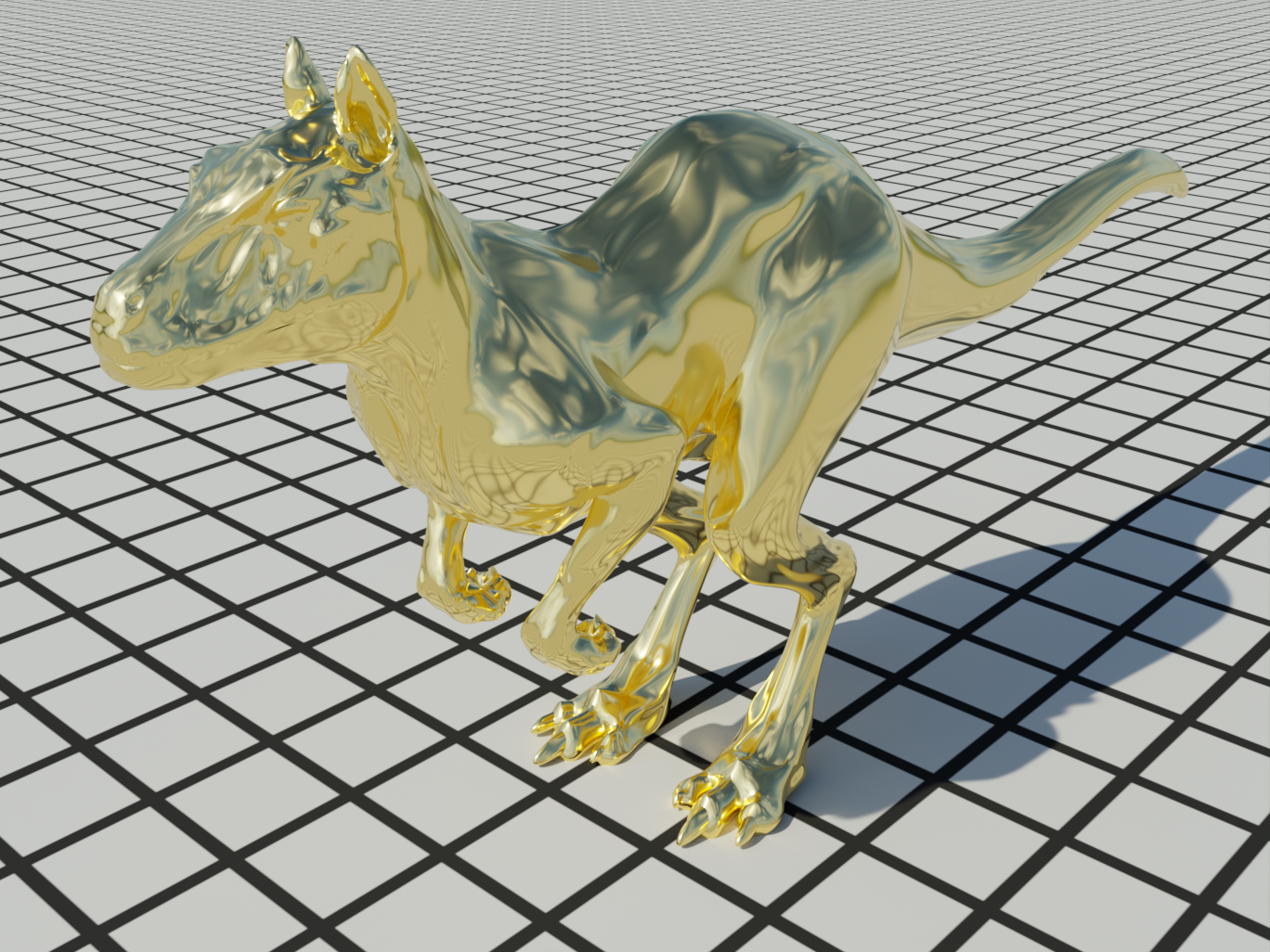
Figure 9.12 shows a plot of the index of refraction and absorption coefficient for gold; both of these are wavelength-dependent quantities. Figure 9.13 shows a model rendered with a metal material.
A wondrous aspect of the Fresnel equations is that these two deceptively simple formulae span all major classes of material behavior including dielectrics, conductors, and semiconductors. In the latter two cases, one must simply evaluate these equations using complex arithmetic. The FrComplex() function realizes this change. It takes the angle cosine of the incident direction and a relative index of refraction obtained using complex division.
Compared to FrDielectric(), the main change in the implementation is the type replacement of Float by pstd::complex<Float>. The function pstd::norm(x) computes the squared magnitude—that is, the square of the distance from the origin of the complex plane to the point .
Computation of using Snell’s law reveals another curious difference: due to the dependence on , this value now generally has an imaginary component, losing its original meaning as the cosine of the transmitted angle.
This is expected in the case of the Fresnel equations—computation of the actual transmitted angle in absorbing materials is more involved, and we sidestep this case in pbrt (recall that conductors were assumed to be opaque).
Complex numbers play a larger role within the Fresnel equations when polarization is modeled: recall how we detected the total internal reflection when a number under a square root became negative, which is nonsensical in real arithmetic. With complex arithmetic, this imaginary square root can be computed successfully. The angles of the resulting complex numbers and relative to the origin of the complex plane encode a delay (also known as the phase) that influences the polarization state of the reflected superposition of parallel and perpendicularly polarized waves. It is also worth noting that a number of different sign conventions exist—for example, depending on the definition of a plane wave, the imaginary IOR component k of conductors is either positive or negative. Some sources also flip the sign of the component. Such subtle details are a common source of bugs in renderers that account for polarization, but they are of no concern for pbrt since it only requires the amplitude of the reflected wave.
Before turning to BxDFs using the helper functions defined in the last subsections, we define a convenient wrapper around FrComplex() that takes a spectrally varying complex IOR split into the eta and k, evaluating it NSpectrumSamples times.