9.5 Dielectric BSDF
In the dielectric case, the relative index of refraction is real-valued, and specular transmission must be considered in addition to reflection. The DielectricBxDF handles this scenario for smooth and rough interfaces.
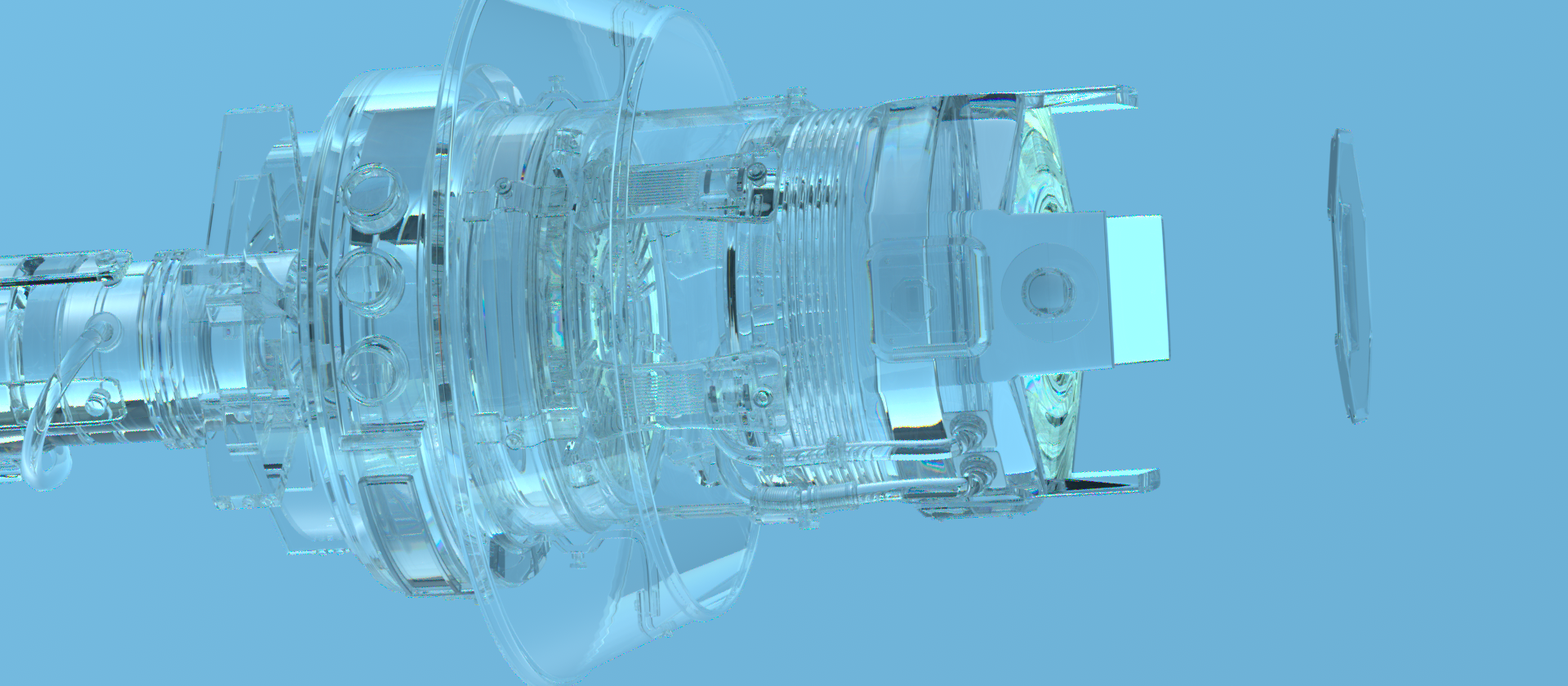
Figure 9.14 shows an image of an abstract model using this BxDF to model a glass material.

The constructor takes a single Float-valued eta parameter and a microfacet distribution mfDistrib. Spectrally varying IORs that disperse light into different directions are handled by randomly sampling a single wavelength to follow and then instantiating a corresponding DielectricBxDF. Section 10.5.1 discusses this topic in more detail.
The Flags() method handles three different cases. The first is when the dielectric interface is index-matched—that is, with an equal IOR on both sides (in which case )—and light is only transmitted. Otherwise, in the other two cases, the BSDF has both reflected and transmitted components. In both of these cases, the TrowbridgeReitzDistribution’s EffectivelySmooth() method differentiates between specular and glossy scattering.
The Sample_f() method must choose between sampling perfect specular reflection or transmission. As before, we postpone handling of rough surfaces and only discuss the perfect specular case for now.
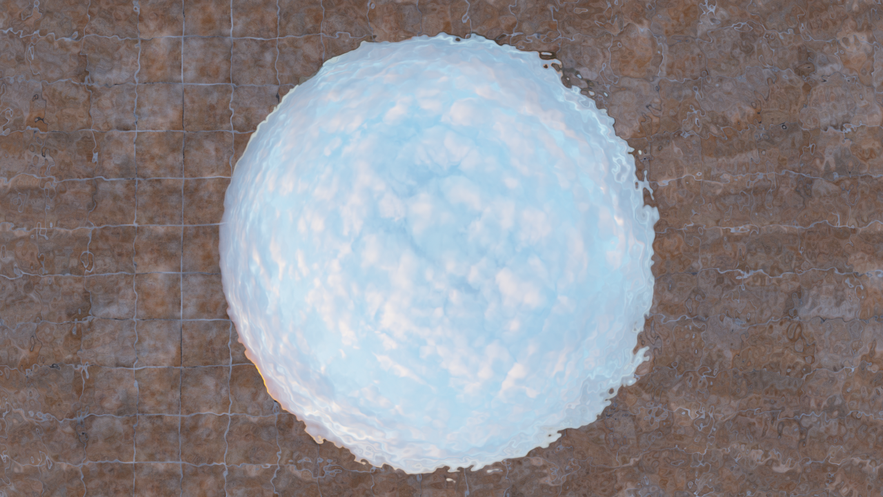
Since dielectrics are characterized by both reflection and transmission, the sampling scheme must randomly choose between these two components, which influences the density function. While any discrete distribution is in principle admissible, an efficient approach from a Monte Carlo variance standpoint is to sample according to the contribution that these two components make—in other words, proportional to the Fresnel reflectance R and the complementary transmittance 1-R. Figure 9.15 shows the benefit of sampling in this way compared to an equal split between reflection and transmission.
Because BSDF components can be selectively enabled or disabled via the sampleFlags argument, the component choice is based on adjusted probabilities pr and pt that take this into account.
In the most common case where both reflection and transmission are sampled, the BSDF value and sample probability contain the common factor R or T, which cancels when their ratio is taken. Thus, all sampled rays end up making the same contribution, and the Fresnel factor manifests in the relative proportion of reflected and transmitted rays.
Putting all of this together, the only change in the following code compared to the analogous fragment <<Sample perfect specular conductor BRDF>> is the incorporation of the discrete probability of the sample.
Specular transmission is handled along similar lines, though using the refracted ray direction for wi. The equation for the corresponding BTDF is similar to the case for perfect specular reflection, Equation (9.9), though there is an additional subtle technical detail: depending on the IOR , refraction either compresses or expands radiance in the angular domain, and the implementation must scale ft to account for this. This correction does not change the amount of radiant power in the scene—rather, it models how the same power is contained in a different solid angle. The details of this step differ depending on the direction of propagation in bidirectional rendering algorithms, and we therefore defer the corresponding fragment <<Account for non-symmetry with transmission to different medium>> to Section 9.5.2.
The function Refract() computes the refracted direction wi via Snell’s law, which fails in the case of total internal reflection. In principle, this should never happen: the transmission case is sampled with probability T, which is zero in the case of total internal reflection. However, due to floating-point rounding errors, inconsistencies can occasionally arise here. We handle this corner case by returning an invalid sample.
As with the ConductorBxDF, zero is returned from the f() method if the interface is smooth and all scattering is perfect specular.
Also, a PDF value of zero is returned if the BSDF is represented using delta distributions.
The missing three fragments—<<Sample rough dielectric BSDF>>, <<Evaluate rough dielectric BSDF>>, and <<Evaluate sampling PDF of rough dielectric BSDF>>—will be presented in Section 9.7.
9.5.1 Thin Dielectric BSDF
Dielectric interfaces rarely occur in isolation: a particularly common configuration involves two nearby index of refraction changes that are smooth, locally parallel, and mutually reciprocal—that is, with relative IOR and a corresponding interface with the inverse . Examples include plate- and acrylic glass in windows or plastic foil used to seal and preserve food.
This important special case is referred to as a thin dielectric due to the spatial proximity of the two interfaces compared to the larger lateral dimensions. When incident light splits into a reflected and a transmitted component with two separate interfaces, it is scattered in a recursive process that traps some of the light within the two interfaces (though this amount progressively decays as it undergoes an increasing number of reflections).
While the internal scattering process within a general dielectric may be daunting, simple analytic solutions can fully describe what happens inside such a thin dielectric—that is, an interface pair satisfying the above simplifying conditions. pbrt provides a specialized BSDF named ThinDielectricBxDF that exploits these insights to efficiently represent an infinite number of internal interactions. It further allows such surfaces to be represented with a single interface, saving the ray intersection expense of tracing ray paths between the two surfaces.
The only parameter to this BxDF is the relative index of refraction of the interior medium.
Since this BxDF models only perfect specular scattering, both its f() and PDF() methods just return zero and are therefore not included here.
The theory of the thin dielectric BSDF goes back to seminal work by Stokes (1860), who investigated light propagation in stacks of glass plates. Figure 9.16 illustrates the most common case involving only a single glass plate: an incident light ray (red) reflects and transmits in proportions and . When the transmitted ray encounters the bottom interface, reciprocity causes it to reflect and transmit according to the same proportions. This process repeats in perpetuity.
Of course, rays beyond the first interaction are displaced relative to the entrance point. Due to the assumption of a thin dielectric, this spatial shift is considered to be negligible; only the total amount of reflected or transmitted light matters. By making this simplification, it is possible to aggregate the effect of the infinite number of scattering events into a simple modification of the reflectance and transmittance factors.
Consider the paths that are reflected out from the top layer. Their aggregate reflectance is given by a geometric series that can be converted into an explicit form:
A similar series gives how much light is transmitted, but it can be just as easily computed as , due to energy conservation. Figure 9.17 plots and as a function of incident angle . The second interface has the effect of increasing the overall amount of reflection compared to a single Fresnel interaction.
The Sample_f() method computes the and coefficients and then computes probabilities for sampling reflection and transmission, just as the DielectricBxDF did, reusing the corresponding code fragment.
The updated reflection and transmission coefficients are easily computed using Equation (9.10), though care must be taken to avoid a division by zero in the case of .
The DielectricBxDF fragment that samples perfect specular reflection is also reused in this method’s implementation, inheriting the computed R value. The transmission case slightly deviates from the DielectricBxDF, as the transmitted direction is simply the negation of wo.
9.5.2 Non-Symmetric Scattering and Refraction

All physically based BRDFs are symmetric: the incident and outgoing directions can be interchanged without changing the function’s value. However, the same is not generally true for BTDFs. Non-symmetry with BTDFs is due to the fact that when light refracts into a material with a higher index of refraction than the incident medium’s index of refraction, energy is compressed into a smaller set of angles (and vice versa, when going in the opposite direction). This effect is easy to see yourself, for instance, by looking at the sky from underwater in a quiet outdoor swimming pool. Because no light can be refracted above the critical angle ( for water), the incident hemisphere of light is squeezed into a considerably smaller subset of the hemisphere, which covers the remaining set of angles (Figure 9.18). Radiance along rays that do refract therefore must increase so that energy is preserved when light passes through the interface.
More formally, consider incident radiance arriving at the boundary between two media, with indices of refraction and (Figure 9.19). Assuming for now that all the incident light is transmitted, the amount of transmitted differential flux is then
Expanding the solid angles to spherical angles gives
or
Substituting both Snell’s law and this relationship into Equation (9.11) and then simplifying, we have
Finally, , which gives the final relationship between incident and transmitted radiance:
The symmetry relationship satisfied by a BTDF is thus
Non-symmetric scattering can be particularly problematic for bidirectional light transport algorithms that sample light paths starting both from the camera and from the lights. If non-symmetry is not accounted for, then such algorithms may produce incorrect results, since the design of such algorithms is fundamentally based on the principle of symmetry.
We will say that light paths sampled starting from the lights carry importance while paths starting from the camera carry radiance. These terms correspond to the quantity that is recorded at a path’s starting point. With importance transport, the incident and outgoing direction arguments of the BSDFs will be (incorrectly) reversed unless special precautions are taken.
We thus define the adjoint BSDF , whose only role is to evaluate the original BSDF with swapped arguments:
All sampling steps based on importance transport use the adjoint form of the BSDF rather than its original version. Most BSDFs in pbrt are symmetric so that there is no actual difference between and . However, non-symmetric cases require additional attention.
The TransportMode enumeration is used to inform such non-symmetric BSDFs about the transported quantity so that they can correctly switch between the adjoint and non-adjoint forms.
The adjoint BTDF is then
which effectively cancels out the scale factor in Equation (9.12).
With these equations, we can now define the remaining missing piece in the implementation of the DielectricBxDF evaluation and sampling methods. Whenever radiance is transported over a refractive boundary, we apply the scale factor from Equation (9.12). For importance transport, we use the adjoint BTDF, which lacks the scaling factor due to the combination of Equations (9.12) and (9.13).