10.2 Texture Coordinate Generation
Almost all of the textures in this chapter are functions that take a 2D or 3D coordinate and return a texture value. Sometimes there are obvious ways to choose these texture coordinates; for parametric surfaces, such as the quadrics in Chapter 3, there is a natural 2D parameterization of the surface, and for all surfaces the shading point is a natural choice for a 3D coordinate.
In other cases, there is no natural parameterization, or the natural parameterization may be undesirable. For instance, the values near the poles of spheres are severely distorted. Also, for an arbitrary subdivision surface, there is no simple, general-purpose way to assign texture values so that the entire space is covered continuously and without distortion. In fact, creating smooth parameterizations of complex meshes with low distortion is an active area of research in computer graphics.
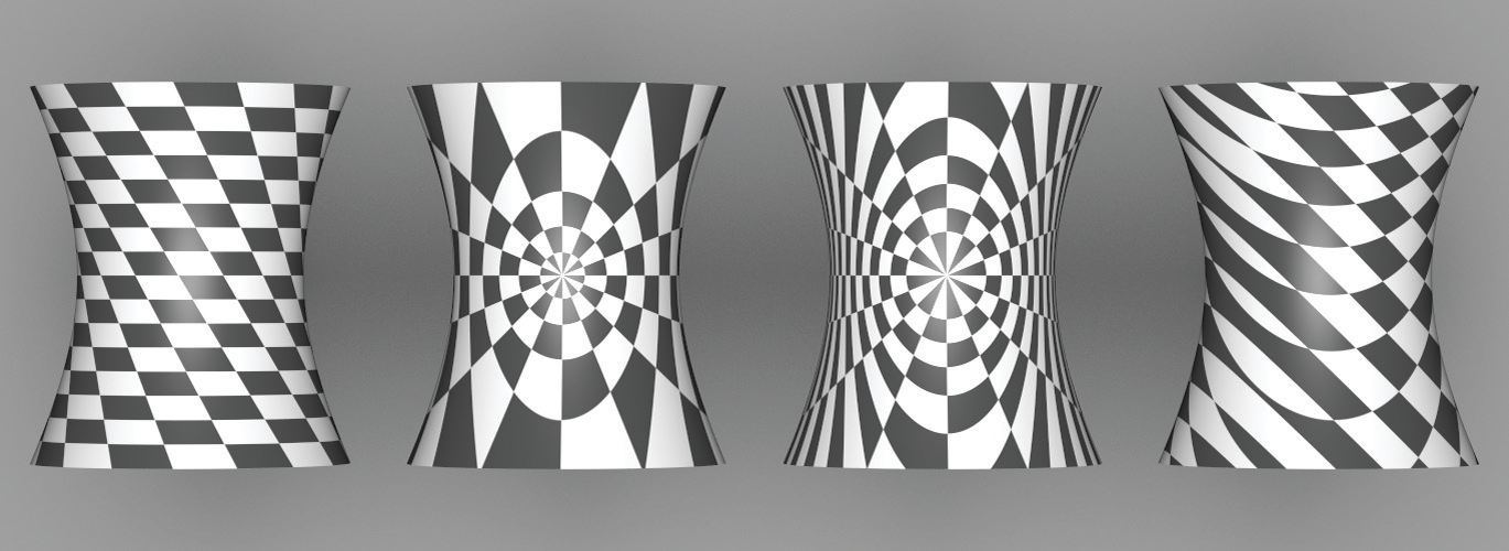
This section starts by introducing two abstract base classes—TextureMapping2D and TextureMapping3D—that provide an interface for computing these 2D and 3D texture coordinates. We will then implement a number of standard mappings using this interface (Figure 10.7 shows a number of them).

Texture implementations store a pointer to a 2D or 3D mapping function as appropriate and use it to compute the texture coordinates at each point. Thus, it’s easy to add new mappings to the system without having to modify all of the Texture implementations, and different mappings can be used for different textures associated with the same surface. In pbrt, we will use the convention that 2D texture coordinates are denoted by ; this helps make clear the distinction between the intrinsic parameterization of the underlying surface and the (possibly different) coordinate values used for texturing.
The TextureMapping2D base class has a single method, TextureMapping2D::Map(), which is given the SurfaceInteraction at the shading point and returns the texture coordinates via a Point2f. It also returns estimates for the change in with respect to pixel and coordinates in the dstdx and dstdy parameters so that textures that use the mapping can determine the sampling rate and filter accordingly.
10.2.1 2D Mapping
The simplest mapping uses the coordinates in the SurfaceInteraction to compute the texture coordinates. Their values can be offset and scaled with user-supplied values in each dimension.
The scale-and-shift computation to compute coordinates is straightforward:
Computing the differential change in and in terms of the original change in and and the scale amounts is also easy. Using the chain rule,
and similarly for the three other partial derivatives. From the mapping method,
so
and thus
and so forth.
10.2.2 Spherical Mapping
Another useful mapping effectively wraps a sphere around the object. Each point is projected along the vector from the sphere’s center through the point, up to the sphere’s surface. There, the mapping for the sphere shape is used. The SphericalMapping2D stores a transformation that is applied to points before this mapping is performed; this effectively allows the mapping sphere to be arbitrarily positioned and oriented with respect to the object.
A short utility function computes the mapping for a single point. It will be useful to have this logic separated out for computing texture coordinate differentials.
We could use the chain rule again to compute the texture coordinate differentials but will instead use a forward differencing approximation to demonstrate another way to compute these values that is useful for more complex mapping functions. Recall that the SurfaceInteraction stores the screen space partial derivatives and that give the change in position as a function of change in image sample position. Therefore, if the coordinate is computed by some function , it’s easy to compute approximations like
As the distance approaches , this gives the actual partial derivative at .
One other detail is that the sphere mapping has a discontinuity in the mapping formula; there is a seam at , where the texture coordinate discontinuously jumps back to zero. We can detect this case by checking to see if the absolute value of the estimated derivative computed with forward differencing is greater than and then adjusting it appropriately.
10.2.3 Cylindrical Mapping
The cylindrical mapping effectively wraps a cylinder around the object. It also supports a transformation to orient the mapping cylinder.
The cylindrical mapping has the same basic structure as the sphere mapping; just the mapping function is different. Therefore, we will omit the fragment that computes texture coordinate differentials, since it is essentially the same as the spherical version.
10.2.4 Planar Mapping
Another classic mapping method is planar mapping. The point is effectively projected onto a plane; a 2D parameterization of the plane then gives texture coordinates for the point. For example, a point might be projected onto the plane to yield texture coordinates given by and .
In general, we can define such a parameterized plane with two nonparallel vectors and and offsets and . The texture coordinates are given by the coordinates of the point with respect to the plane’s coordinate system, which are computed by taking the dot product of the vector from the point to the origin with each vector and and then adding the offset. For the example in the previous paragraph, we’d have , , and .
The planar mapping differentials can be computed directly by finding the differentials of the point in texture coordinate space.
10.2.5 3D Mapping
We will also define a TextureMapping3D class that defines the interface for generating 3D texture coordinates.
The natural 3D mapping just takes the world space coordinate of the point and applies a linear transformation to it. This will often be a transformation that takes the point back to the primitive’s object space.
Because a linear mapping is used, the differential change in texture coordinates can be found by applying the same mapping to the partial derivatives of position.