12.3 Point Lights

A number of interesting lights can be described in terms of emission from a single point in space with some possibly angularly varying distribution of outgoing light. This section describes the implementation of a number of them, starting with PointLight, which represents an isotropic point light source that emits the same amount of light in all directions. It is defined in lights/point.h and lights/point.cpp. Figure 12.6 shows a scene rendered with a point light source. Building on this base, a number of more complex lights based on point sources will be introduced, including spotlights and a light that projects an image into the scene.

Figure 12.6: Scene Rendered with a Point Light Source. Notice the hard shadow boundaries from this type of light.

<<PointLight Declarations>>= 
class PointLight : public Light { public: <<PointLight Public Methods>> 
PointLight(const Transform &LightToWorld, const MediumInterface &mediumInterface, const Spectrum &I) : Light((int)LightFlags::DeltaPosition, LightToWorld, mediumInterface), pLight(LightToWorld(Point3f(0, 0, 0))), I(I) { } Spectrum Sample_Li(const Interaction &ref, const Point2f &u, Vector3f *wi, Float *pdf, VisibilityTester *vis) const; Spectrum Power() const; Float Pdf_Li(const Interaction &, const Vector3f &) const; Spectrum Sample_Le(const Point2f &u1, const Point2f &u2, Float time, Ray *ray, Normal3f *nLight, Float *pdfPos, Float *pdfDir) const; void Pdf_Le(const Ray &, const Normal3f &, Float *pdfPos, Float *pdfDir) const;
private: <<PointLight Private Data>> 
const Point3f pLight; const Spectrum I;
};

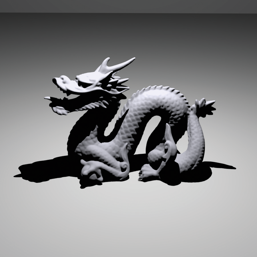
PointLights are positioned at the origin in light space. To place them elsewhere, the light-to-world transformation should be set appropriately. Using this transformation, the world space position of the light is precomputed and cached in the constructor by transforming left-parenthesis 0 comma 0 comma 0 right-parenthesis from light space to world space.

The constructor also stores the intensity for the light source, which is the amount of power per unit solid angle. Because the light source is isotropic, this is a constant. Finally, since point lights represent singularities that only emit light from a single position, the Light::flags field is initialized to LightFlags::DeltaPosition.

<<PointLight Public Methods>>= 
PointLight(const Transform &LightToWorld, const MediumInterface &mediumInterface, const Spectrum &I) : Light((int)LightFlags::DeltaPosition, LightToWorld, mediumInterface), pLight(LightToWorld(Point3f(0, 0, 0))), I(I) { }

<<PointLight Private Data>>= 
const Point3f pLight; const Spectrum I;

Strictly speaking, it is incorrect to describe the light arriving at a point due to a point light source using units of radiance. Radiant intensity is instead the proper unit for describing emission from a point light source, as explained in Section 5.4. In the light source interfaces here, however, we will abuse terminology and use Sample_Li() methods to report the illumination arriving at a point for all types of light sources, dividing radiant intensity by the squared distance to the point p to convert units. Section 14.2 revisits the details of this issue in its discussion of how delta distributions affect evaluation of the integral in the scattering equation. In the end, the correctness of the computation does not suffer from this fudge, and it makes the implementation of light transport algorithms more straightforward by not requiring them to use different interfaces for different types of lights.

<<PointLight Method Definitions>>= 
Spectrum PointLight::Sample_Li(const Interaction &ref, const Point2f &u, Vector3f *wi, Float *pdf, VisibilityTester *vis) const { *wi = Normalize(pLight - ref.p); *pdf = 1.f; *vis = VisibilityTester(ref, Interaction(pLight, ref.time, mediumInterface)); return I / DistanceSquared(pLight, ref.p); }

The total power emitted by the light source can be found by integrating the intensity over the entire sphere of directions:

normal upper Phi equals integral Underscript script upper S squared Endscripts upper I normal d omega Subscript Baseline equals upper I integral Underscript script upper S squared Endscripts normal d omega Subscript Baseline equals 4 pi upper I period

<<PointLight Method Definitions>>+=  
Spectrum PointLight::Power() const { return 4 * Pi * I; }

12.3.1 Spotlights

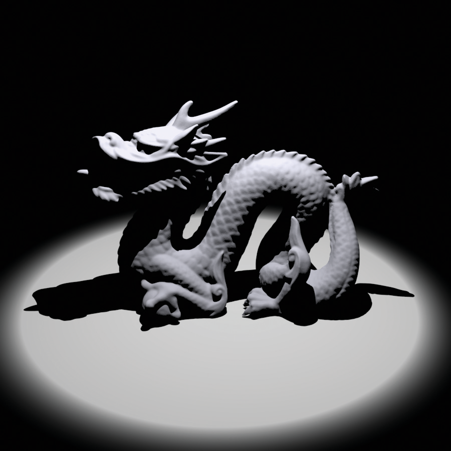
Spotlights are a handy variation on point lights; rather than shining illumination in all directions, they emit light in a cone of directions from their position. For simplicity, we will define the spotlight in the light coordinate system to always be at position left-parenthesis 0 comma 0 comma 0 right-parenthesis and pointing down the plus z axis. To place or orient it elsewhere in the scene, the Light::WorldToLight transformation should be set accordingly. Figure 12.7 shows a rendering of the same scene as Figure 12.6, only illuminated with a spotlight instead of a point light. The SpotLight class is defined in lights/spot.h and lights/spot.cpp.

Figure 12.7: Scene Rendered with a Spotlight. The spotlight cone smoothly cuts off illumination past a user-specified angle from the light’s central axis.

<<SpotLight Declarations>>= 
class SpotLight : public Light { public: <<SpotLight Public Methods>> 
SpotLight(const Transform &LightToWorld, const MediumInterface &m, const Spectrum &I, Float totalWidth, Float falloffStart); Spectrum Sample_Li(const Interaction &ref, const Point2f &u, Vector3f *wi, Float *pdf, VisibilityTester *vis) const; Float Falloff(const Vector3f &w) const; Spectrum Power() const; Float Pdf_Li(const Interaction &, const Vector3f &) const; Spectrum Sample_Le(const Point2f &u1, const Point2f &u2, Float time, Ray *ray, Normal3f *nLight, Float *pdfPos, Float *pdfDir) const; void Pdf_Le(const Ray &, const Normal3f &, Float *pdfPos, Float *pdfDir) const;
private: <<SpotLight Private Data>> 
const Point3f pLight; const Spectrum I; const Float cosTotalWidth, cosFalloffStart;
};

Two angles are passed to the constructor to set the extent of the SpotLight’s cone: the overall angular width of the cone and the angle at which falloff starts (Figure 12.8). The constructor precomputes and stores the cosines of these angles for use in the SpotLight’s methods.

Figure 12.8: Spotlights are defined by two angles, falloffStart and totalWidth. Objects inside the inner cone of angles, up to falloffStart, are fully illuminated by the light. The directions between falloffStart and totalWidth are a transition zone that ramps down from full illumination to no illumination, such that points outside the totalWidth cone aren’t illuminated at all. The cosine of the angle between the vector to a point p and the spotlight axis, theta , can easily be computed with a dot product.

<<SpotLight Method Definitions>>= 
SpotLight::SpotLight(const Transform &LightToWorld, const MediumInterface &mediumInterface, const Spectrum &I, Float totalWidth, Float falloffStart) : Light((int)LightFlags::DeltaPosition, LightToWorld, mediumInterface), pLight(LightToWorld(Point3f(0, 0, 0))), I(I), cosTotalWidth(std::cos(Radians(totalWidth))), cosFalloffStart(std::cos(Radians(falloffStart))) { }

<<SpotLight Private Data>>= 
const Point3f pLight; const Spectrum I; const Float cosTotalWidth, cosFalloffStart;

The SpotLight::Sample_Li() method is almost identical to PointLight::Sample_Li(), except that it also calls the Falloff() method, which computes the distribution of light accounting for the spotlight cone. This computation is encapsulated in a separate method since other SpotLight methods will need to perform it as well.

<<SpotLight Method Definitions>>+=  
Spectrum SpotLight::Sample_Li(const Interaction &ref, const Point2f &u, Vector3f *wi, Float *pdf, VisibilityTester *vis) const { *wi = Normalize(pLight - ref.p); *pdf = 1.f; *vis = VisibilityTester(ref, Interaction(pLight, ref.time, mediumInterface)); return I * Falloff(-*wi) / DistanceSquared(pLight, ref.p); }

To compute the spotlight’s strength for a receiving point normal p Subscript , this first step is to compute the cosine of the angle between the vector from the spotlight origin to normal p Subscript and the vector along the center of the spotlight’s cone. To compute the cosine of the offset angle to a point p, we have, as illustrated in Figure 12.8,

StartLayout 1st Row 1st Column cosine theta 2nd Column equals left-parenthesis normal p Subscript Baseline minus left-parenthesis 0 comma 0 comma 0 right-parenthesis right-parenthesis dot left-parenthesis 0 comma 0 comma 1 right-parenthesis 2nd Row 1st Column Blank 2nd Column equals normal p Subscript Baseline Subscript z Baseline slash double-vertical-bar bold p double-vertical-bar period EndLayout

This value is then compared to the cosines of the falloff and overall width angles to see where the point lies with respect to the spotlight cone. We can trivially determine that points with a cosine greater than the cosine of the falloff angle are inside the cone receiving full illumination, and points with cosine less than the width angle’s cosine are completely outside the cone. (Note that the computation is slightly tricky since for theta element-of left-bracket 0 comma pi right-bracket , if theta greater-than theta prime , then cosine theta less-than cosine theta prime .)

<<SpotLight Method Definitions>>+=  
Float SpotLight::Falloff(const Vector3f &w) const { Vector3f wl = Normalize(WorldToLight(w)); Float cosTheta = wl.z; if (cosTheta < cosTotalWidth) return 0; if (cosTheta > cosFalloffStart) return 1; <<Compute falloff inside spotlight cone>> 
Float delta = (cosTheta - cosTotalWidth) / (cosFalloffStart - cosTotalWidth); return (delta * delta) * (delta * delta);
}

For points inside the transition range from fully illuminated to outside of the cone, the intensity is scaled to smoothly fall off from full illumination to darkness:

<<Compute falloff inside spotlight cone>>= 
Float delta = (cosTheta - cosTotalWidth) / (cosFalloffStart - cosTotalWidth); return (delta * delta) * (delta * delta);

The solid angle subtended by a cone with spread angle theta is 2 pi left-parenthesis 1 minus cosine theta right-parenthesis . Therefore, the integral over directions on the sphere that gives power from radiant intensity can be solved to compute the total power of a light that only emits illumination in a cone. For the spotlight, we can reasonably approximate the power of the light by computing the solid angle of directions that is covered by the cone with a spread angle cosine halfway between falloffWidth and falloffStart.

<<SpotLight Method Definitions>>+=  
Spectrum SpotLight::Power() const { return I * 2 * Pi * (1 - .5f * (cosFalloffStart + cosTotalWidth)); }

12.3.2 Texture Projection Lights

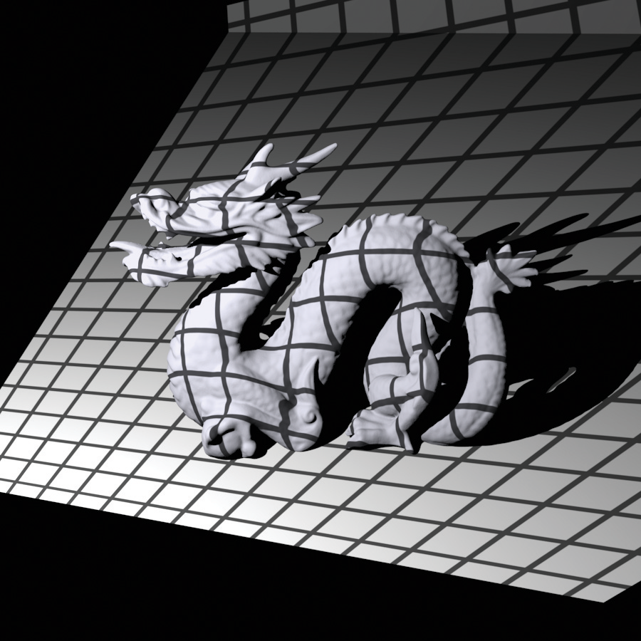
Another useful light source acts like a slide projector; it takes an image map and projects its image out into the scene. The ProjectionLight class uses a projective transformation to project points in the scene onto the light’s projection plane based on the field of view angle given to the constructor (Figure 12.9). Its implementation is in lights/projection.h and lights/projection.cpp.

Figure 12.9: The Basic Setting for Projection Light Sources. A point normal p Subscript in the light’s coordinate system is projected onto the plane of the image using the light’s projection matrix.

The use of this light in the lighting example scene is shown in Figure 12.10.

Figure 12.10: Scene Rendered with a Projection Light Using a Grid Texture Map. The projection light acts like a slide projector, projecting an image onto objects in the scene.

<<ProjectionLight Declarations>>= 
class ProjectionLight : public Light { public: <<ProjectionLight Public Methods>> 
ProjectionLight(const Transform &LightToWorld, const MediumInterface &medium, const Spectrum &I, const std::string &texname, Float fov); Spectrum Sample_Li(const Interaction &ref, const Point2f &u, Vector3f *wi, Float *pdf, VisibilityTester *vis) const; Spectrum Projection(const Vector3f &w) const; Spectrum Power() const; Float Pdf_Li(const Interaction &, const Vector3f &) const; Spectrum Sample_Le(const Point2f &u1, const Point2f &u2, Float time, Ray *ray, Normal3f *nLight, Float *pdfPos, Float *pdfDir) const; void Pdf_Le(const Ray &, const Normal3f &, Float *pdfPos, Float *pdfDir) const;
private: <<ProjectionLight Private Data>> 
std::unique_ptr<MIPMap<RGBSpectrum>> projectionMap; const Point3f pLight; const Spectrum I; Transform lightProjection; Float near, far; Bounds2f screenBounds; Float cosTotalWidth;
};

<<ProjectionLight Method Definitions>>= 
ProjectionLight::ProjectionLight(const Transform &LightToWorld, const MediumInterface &mediumInterface, const Spectrum &I, const std::string &texname, Float fov) : Light((int)LightFlags::DeltaPosition, LightToWorld, mediumInterface), pLight(LightToWorld(Point3f(0, 0, 0))), I(I) { <<Create ProjectionLight MIP map>> 
Point2i resolution; std::unique_ptr<RGBSpectrum[]> texels = ReadImage(texname, &resolution); if (texels) projectionMap.reset(new MIPMap<RGBSpectrum>(resolution, texels.get()));
<<Initialize ProjectionLight projection matrix>> 
Float aspect = projectionMap ? (Float(resolution.x) / Float(resolution.y)) : 1; if (aspect > 1) screenBounds = Bounds2f(Point2f(-aspect, -1), Point2f(aspect, 1)); else screenBounds = Bounds2f(Point2f(-1, -1/aspect), Point2f(1, 1/aspect)); near = 1e-3f; far = 1e30f; lightProjection = Perspective(fov, near, far);
<<Compute cosine of cone surrounding projection directions>> 
Float opposite = std::tan(Radians(fov) / 2.f); Float tanDiag = opposite * std::sqrt(1 + 1 / (aspect * aspect)); cosTotalWidth = std::cos(std::atan(tanDiag));
}

This light could use a Texture to represent the light projection distribution so that procedural projection patterns could be used. However, having a precise representation of the projection function, as is available by using an image in a MIPMap, is useful for being able to sample the projection distribution using Monte Carlo techniques, so we will use that representation in the implementation here.

Note that the projected image is explicitly stored as an RGBSpectrum, even if full spectral rendering is being performed. Unless the image map being used has full spectral data, storing full SampledSpectrum values in this case only wastes memory; whether an RGB color is converted to a SampledSpectrum before the MIPMap is created or after the MIPMap returns a value from its Lookup() routine gives the same result in either case.

<<Create ProjectionLight MIP map>>= 
Point2i resolution; std::unique_ptr<RGBSpectrum[]> texels = ReadImage(texname, &resolution); if (texels) projectionMap.reset(new MIPMap<RGBSpectrum>(resolution, texels.get()));

<<ProjectionLight Private Data>>= 
std::unique_ptr<MIPMap<RGBSpectrum>> projectionMap; const Point3f pLight; const Spectrum I;

Similar to the PerspectiveCamera, the ProjectionLight constructor computes a projection matrix and the screen space extent of the projection.

<<Initialize ProjectionLight projection matrix>>= 
Float aspect = projectionMap ? (Float(resolution.x) / Float(resolution.y)) : 1; if (aspect > 1) screenBounds = Bounds2f(Point2f(-aspect, -1), Point2f(aspect, 1)); else screenBounds = Bounds2f(Point2f(-1, -1/aspect), Point2f(1, 1/aspect)); near = 1e-3f; far = 1e30f; lightProjection = Perspective(fov, near, far);

<<ProjectionLight Private Data>>+=  
Transform lightProjection; Float near, far; Bounds2f screenBounds;

Finally, the constructor finds the cosine of the angle between the plus z axis and the vector to a corner of the screen window. This value is used elsewhere to define the minimal cone of directions that encompasses the set of directions in which light is projected. This cone is useful for algorithms like photon mapping that need to randomly sample rays leaving the light source (explained in Chapter 16). We won’t derive this computation here; it is based on straightforward trigonometry.

<<Compute cosine of cone surrounding projection directions>>= 
Float opposite = std::tan(Radians(fov) / 2.f); Float tanDiag = opposite * std::sqrt(1 + 1 / (aspect * aspect)); cosTotalWidth = std::cos(std::atan(tanDiag));

<<ProjectionLight Private Data>>+= 
Float cosTotalWidth;

Similar to the spotlight’s version, ProjectionLight::Sample_Li() calls a utility method, ProjectionLight::Projection(), to determine how much light is projected in the given direction. Therefore, we won’t include the implementation of Sample_Li() here.

<<ProjectionLight Method Definitions>>+=  
Spectrum ProjectionLight::Projection(const Vector3f &w) const { Vector3f wl = WorldToLight(w); <<Discard directions behind projection light>> 
if (wl.z < near) return 0;
<<Project point onto projection plane and compute light>> 
Point3f p = lightProjection(Point3f(wl.x, wl.y, wl.z)); if (!Inside(Point2f(p.x, p.y), screenBounds)) return 0.f; if (!projectionMap) return 1; Point2f st = Point2f(screenBounds.Offset(Point2f(p.x, p.y))); return Spectrum(projectionMap->Lookup(st), SpectrumType::Illuminant);
}

Because the projective transformation has the property that it projects points behind the center of projection to points in front of it, it is important to discard points with a negative z value. Therefore, the projection code immediately returns no illumination for projection points that are behind the near plane for the projection. If this check were not done, then it wouldn’t be possible to know if a projected point was originally behind the light (and therefore not illuminated) or in front of it.

<<Discard directions behind projection light>>= 
if (wl.z < near) return 0;

After being projected to the projection plane, points with coordinate values outside the screen window are discarded. Points that pass this test are transformed to get left-parenthesis s comma t right-parenthesis texture coordinates inside left-bracket 0 comma 1 right-bracket squared for the lookup in the image map. Note it is explicitly specified that the RGBSpectrum value passed to the Spectrum constructor represents an illuminant’s SPD and not that of a reflectance. (Recall from Section 5.2.2 that different matching functions are used for converting from RGB to SPDs for illuminants versus reflectances.)

<<Project point onto projection plane and compute light>>= 
Point3f p = lightProjection(Point3f(wl.x, wl.y, wl.z)); if (!Inside(Point2f(p.x, p.y), screenBounds)) return 0.f; if (!projectionMap) return 1; Point2f st = Point2f(screenBounds.Offset(Point2f(p.x, p.y))); return Spectrum(projectionMap->Lookup(st), SpectrumType::Illuminant);

The total power of this light is approximated as a spotlight that subtends the same angle as the diagonal of the projected image, scaled by the average intensity in the image map. This approximation becomes increasingly inaccurate as the projected image’s aspect ratio becomes less square, for example, and it doesn’t account for the fact that texels toward the edges of the image map subtend a larger solid angle than texels in the middle when projected with a perspective projection. Nevertheless, it’s a reasonable first-order approximation.

<<ProjectionLight Method Definitions>>+= 
Spectrum ProjectionLight::Power() const { return (projectionMap ? Spectrum(projectionMap->Lookup(Point2f(.5f, .5f), .5f), SpectrumType::Illuminant) : Spectrum(1.f)) * I * 2 * Pi * (1.f - cosTotalWidth); }

12.3.3 Goniophotometric Diagram Lights

A goniophotometric diagram describes the angular distribution of luminance from a point light source; it is widely used in illumination engineering to characterize lights. Figure 12.11 shows an example of a goniophotometric diagram in two dimensions. In this section, we’ll implement a light source that uses goniophotometric diagrams encoded in 2D image maps to describe the emission distribution of the light. The implementation is very similar to the point light sources defined previously in this section; it scales the intensity based on the outgoing direction according to the goniophotometric diagram’s values.

Figure 12.11: An Example of a Goniophotometric Diagram Specifying an Outgoing Light Distribution from a Point Light Source in 2D. The emitted intensity is defined in a fixed set of directions on the unit sphere, and the intensity for a given outgoing direction omega Subscript is found by interpolating the intensities of the adjacent samples.

Figure 12.12 shows a few goniophotometric diagrams encoded as image maps.

Figure 12.12: Goniophotometric Diagrams for Real-World Light Sources, Encoded as Image Maps with a Parameterization Based on Spherical Coordinates. (1) A light that mostly illuminates in its up direction, with only a small amount of illumination in the down direction. (2) A light that mostly illuminates in the down direction. (3) A light that casts illumination both above and below.

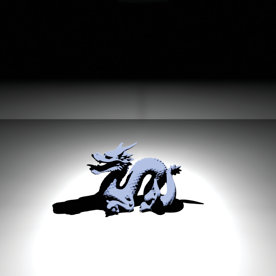
Figure 12.13 shows a scene rendered with a light source that uses one of these images to modulate its directional distribution of illumination.

Figure 12.13: Scene Rendered Using a Goniophotometric Diagram from Figure 12.12. Even though a point light source is the basis of this light, including the directional variation of a realistic light improves the visual realism of the rendered image.

<<GonioPhotometricLight Declarations>>= 
class GonioPhotometricLight : public Light { public: <<GonioPhotometricLight Public Methods>> 
Spectrum Sample_Li(const Interaction &ref, const Point2f &u, Vector3f *wi, Float *pdf, VisibilityTester *vis) const; GonioPhotometricLight(const Transform &LightToWorld, const MediumInterface &mediumInterface, const Spectrum &I, const std::string &texname) : Light((int)LightFlags::DeltaPosition, LightToWorld, mediumInterface), pLight(LightToWorld(Point3f(0, 0, 0))), I(I) { <<Create mipmap for GonioPhotometricLight>> 
Point2i resolution; std::unique_ptr<RGBSpectrum[]> texels = ReadImage(texname, &resolution); if (texels) mipmap.reset(new MIPMap<RGBSpectrum>(resolution, texels.get()));
} Spectrum Scale(const Vector3f &w) const { Vector3f wp = Normalize(WorldToLight(w)); std::swap(wp.y, wp.z); Float theta = SphericalTheta(wp); Float phi = SphericalPhi(wp); Point2f st(phi * Inv2Pi, theta * InvPi); return !mipmap ? RGBSpectrum(1.f) : Spectrum(mipmap->Lookup(st), SpectrumType::Illuminant); } Spectrum Power() const; Float Pdf_Li(const Interaction &, const Vector3f &) const; Spectrum Sample_Le(const Point2f &u1, const Point2f &u2, Float time, Ray *ray, Normal3f *nLight, Float *pdfPos, Float *pdfDir) const; void Pdf_Le(const Ray &, const Normal3f &, Float *pdfPos, Float *pdfDir) const;
private: <<GonioPhotometricLight Private Data>> 
const Point3f pLight; const Spectrum I; std::unique_ptr<MIPMap<RGBSpectrum>> mipmap;
};

The GonioPhotometricLight constructor takes a base intensity and an image map that scales the intensity based on the angular distribution of light.

<<GonioPhotometricLight Public Methods>>= 
GonioPhotometricLight(const Transform &LightToWorld, const MediumInterface &mediumInterface, const Spectrum &I, const std::string &texname) : Light((int)LightFlags::DeltaPosition, LightToWorld, mediumInterface), pLight(LightToWorld(Point3f(0, 0, 0))), I(I) { <<Create mipmap for GonioPhotometricLight>> 
Point2i resolution; std::unique_ptr<RGBSpectrum[]> texels = ReadImage(texname, &resolution); if (texels) mipmap.reset(new MIPMap<RGBSpectrum>(resolution, texels.get()));
}

<<GonioPhotometricLight Private Data>>= 
const Point3f pLight; const Spectrum I; std::unique_ptr<MIPMap<RGBSpectrum>> mipmap;

Like ProjectionLight, GonioPhotometricLight constructs a MIPMap of the distribution’s image map, also always using RGBSpectrum values.

<<Create mipmap for GonioPhotometricLight>>= 
Point2i resolution; std::unique_ptr<RGBSpectrum[]> texels = ReadImage(texname, &resolution); if (texels) mipmap.reset(new MIPMap<RGBSpectrum>(resolution, texels.get()));

The GonioPhotometricLight::Sample_Li() method is not shown here. It is essentially identical to the SpotLight::Sample_Li() and ProjectionLight::Sample_Li() methods that use a helper function to scale the amount of radiance. It assumes that the scale texture is encoded using spherical coordinates, so that the given direction needs to be converted to theta and phi values and scaled to left-bracket 0 comma 1 right-bracket before being used to index into the texture. Goniophotometric diagrams are usually defined in a coordinate space where the y axis is up, whereas the spherical coordinate utility routines in pbrt assume that z is up, so  y and  z are swapped before doing the conversion.

<<GonioPhotometricLight Public Methods>>+= 
Spectrum Scale(const Vector3f &w) const { Vector3f wp = Normalize(WorldToLight(w)); std::swap(wp.y, wp.z); Float theta = SphericalTheta(wp); Float phi = SphericalPhi(wp); Point2f st(phi * Inv2Pi, theta * InvPi); return !mipmap ? RGBSpectrum(1.f) : Spectrum(mipmap->Lookup(st), SpectrumType::Illuminant); }

The Power() method uses the average intensity over the image to compute power. This computation is inaccurate because the spherical coordinate parameterization of directions has various distortions, particularly near the plus z and negative z directions. Again, this error is acceptable for the uses of this method in pbrt.

<<GonioPhotometricLight Method Definitions>>= 
Spectrum GonioPhotometricLight::Power() const { return 4 * Pi * I * Spectrum(mipmap ? mipmap->Lookup(Point2f(.5f, .5f), .5f) : Spectrum(1.f), SpectrumType::Illuminant); }